Fastener tightening system utilizing identification technology

a technology of identification technology and fastener, applied in the direction of force/torque/work measurement apparatus, instruments, manufacturing tools, etc., can solve the problems of reducing the axial load of the first, affecting the compressive force applied to the joint by another already tightening fastener, and reducing the strength of the join

Inactive Publication Date: 2008-07-31
CATERPILLAR INC
View PDF18 Cites 77 Cited by
  • Summary
  • Abstract
  • Description
  • Claims
  • Application Information

AI Technical Summary

Problems solved by technology

Unfortunately, when joints are secured by multiple fasteners, the act of tightening one fastener can affect the compressive force applied to the joint by another already-tightened fastener.
For example, if a first fastener is already tightened to a desired axial load, tightening a second fastener may decrease the axial load of the first fastener, thereby reducing the strength of the joint and increasing the possibility that the joint may fail.
In particular, the Barr system only verifies the torque applied to each fastener and does not account for axial load changes that occur after the fastener has been tightened.
Additionally, although the system in Barr may be capable of applying torques of different magnitudes to different fasteners in the same assembly, this capability only applies to fasteners having different sizes.
Therefore, fasteners having the same size but requiring different torques cannot be accommodated by the Barr system, unless a different socket of the same size is selected.
This limitation may result in unwanted complexity and increased cost.
Because of this, the system may be prone to manufacturing errors such as, for example, mistakenly installing fasteners with a threading geometry incompatible with the components being installed.
Additional assembly errors may include, for example, mistakenly installing fasteners manufactured from inappropriate materials that may perform poorly in the intended application.

Method used


Image

  • Fastener tightening system utilizing identification technology
  • Fastener tightening system utilizing identification technology
  • Fastener tightening system utilizing identification technology

Examples


Embodiment Construction

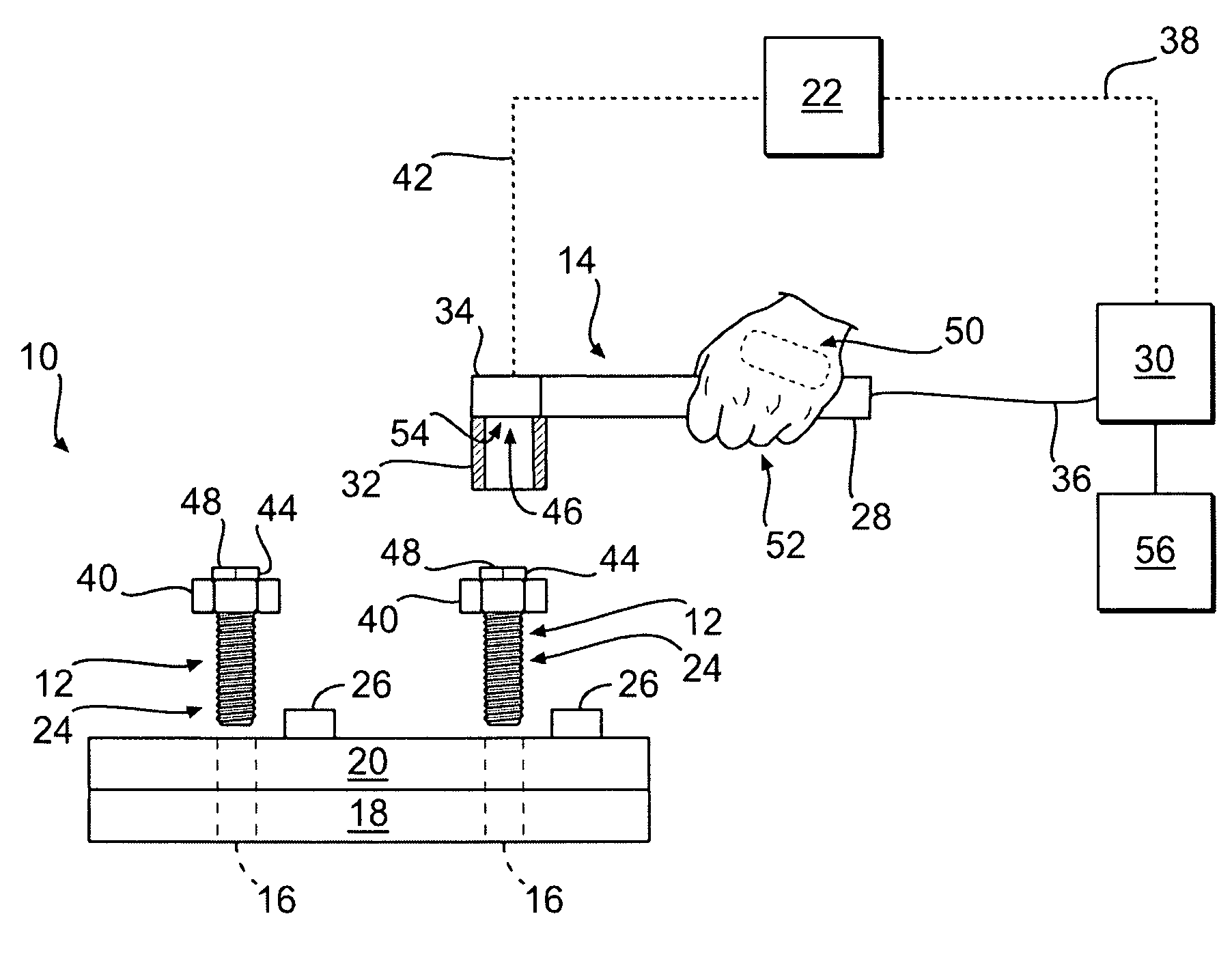
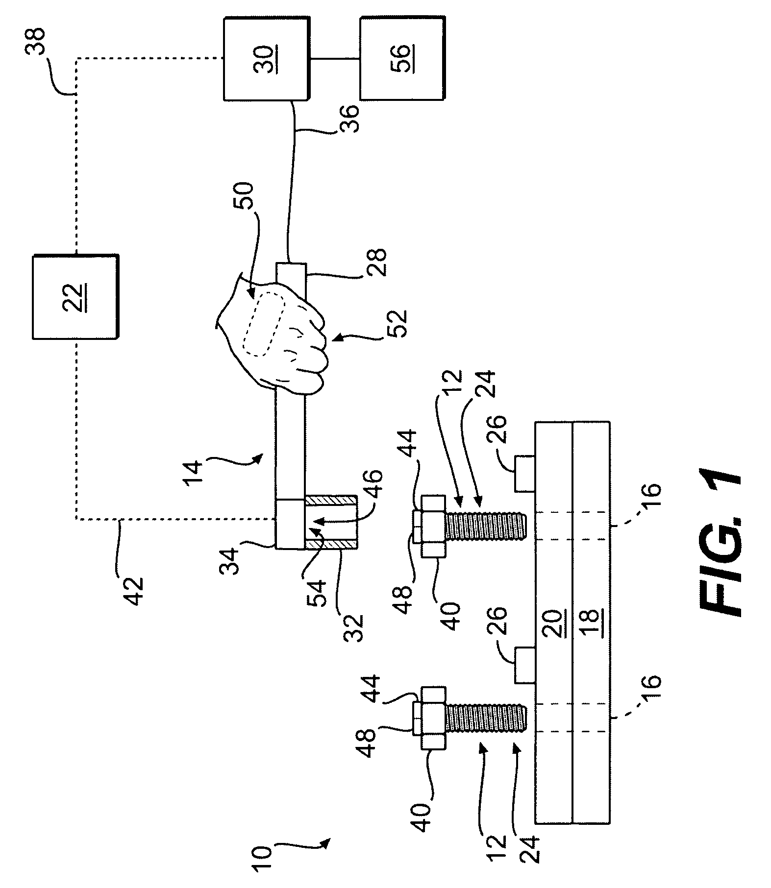
[0018]FIG. 1 provides a diagrammatic perspective of a component assembly station 10 according to an exemplary embodiment. Component assembly station 10 may be used to secure individual components together to create a finished product via one or more mechanical fasteners 12. Such finished products may include, for example, engine assemblies, engine exhaust assemblies, construction equipment, or any other finished product known in the art requiring threaded fasteners to secure individual components together. Mechanical fasteners 12 may be, for example, screws, bolts, threaded studs or lugs, or any other mechanical fastener known in the art. Component assembly station 10 may include a tightening tool 14 for tightening fasteners 12 into mating holes 16 of first and second components 18, 20, and a controller 22 for regulating the operation of tightening tool 14. It should be understood that although the exemplary embodiment illustrated in FIG. 1 discloses two components to be assembled, ...


PUM


Abstract

In one aspect, the present disclosure is directed toward a fastener tightening system. The system has a tightening tool configured to apply a torque to a fastener. Additionally, the system has a fastener data storage device located on the fastener and configured to store data related to the associated fastener. The system further has at least one component data storage device located on a component receiving the fastener to store data related to a tightening process. A data sensor is also included and is configured to sense data stored on the fastener data storage device and the at least one component data storage device. The system also has a controller configured to regulate operation of the tightening tool based on the sensed data and the sensed parameter.

Description

TECHNICAL FIELD[0001]The present disclosure is directed to a fastener tightening system, and more particularly, to a fastener tightening system that utilizes identification technology.BACKGROUND[0002]Conventional manufacturing processes typically involve the assembly of individual components into a finished product. Depending on the intended use of the components and type of joints formed during assembly, several methods and devices can be employed to secure the individual components together. Among the devices commonly used to combine components are mechanical fasteners. Mechanical fasteners grip two or more of the components and effectively use compressive forces to minimize movement between the components.[0003]The strength of joints secured by mechanical fasteners is dependant upon the magnitude of the overall compressive forces applied to the joint, as well as the degree to which the compressive forces acting on the joint are distributed. For example, the joint is strongest whe...

Claims


Application Information

Patent Timeline
Patent Type & Authority Applications(United States)
IPC IPC(8): B25B23/14
CPCB23P19/066B25B23/14B25B21/00
Inventor LONG, ROBERT EARLNASH, JEFFREY P.VENKATA SUKHAVASI, NANDA KISHOREROLEY, JOHN
Owner CATERPILLAR INC
Why Eureka
Try Eureka