
AC/DC system for powering a vehicle

a power system and vehicle technology, applied in the direction of electric generator control, dynamo-electric converter control, multiple dynamo-motor starters, etc., can solve the problems of high cost, no “clear choice” replacement for traditional gasoline-powered vehicles, and very well-known associations with gasoline-powered vehicles

Inactive Publication Date: 2008-07-31
STEGER ANDREW A +1
View PDF13 Cites 5 Cited by
  • Summary
  • Abstract
  • Description
  • Claims
  • Application Information

AI Technical Summary

Benefits of technology

[0006]Other objects and advantages of the present invention will become more obvious hereinafter in the specification and drawings.
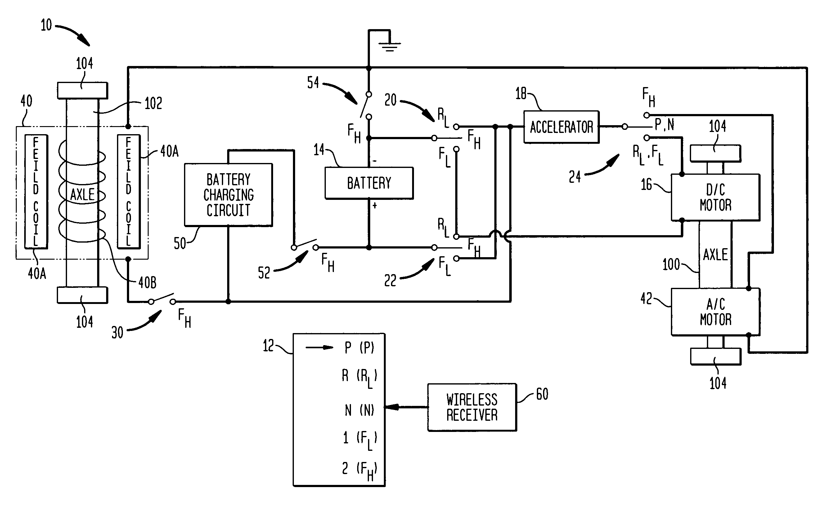
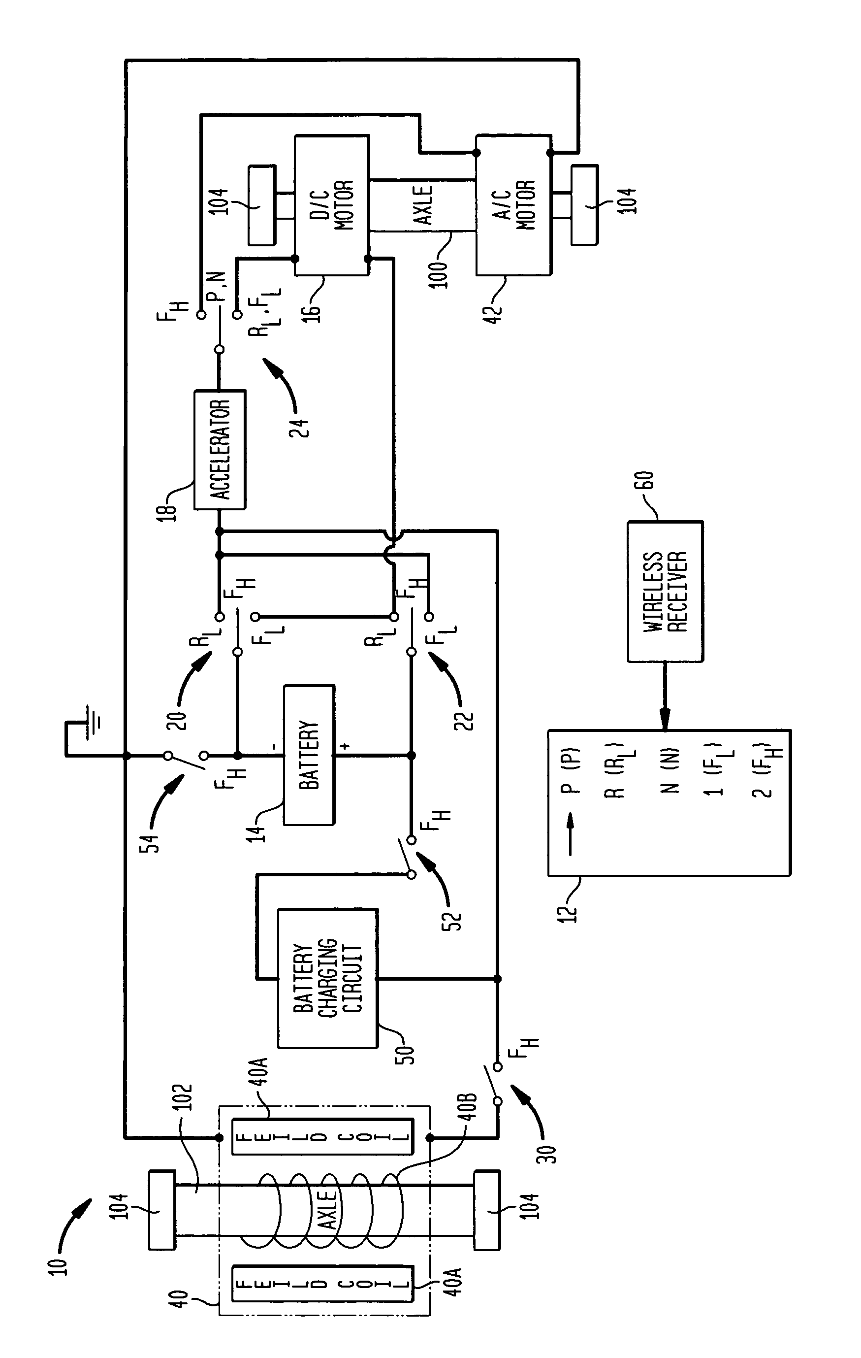
[0007]In accordance with the present invention, a system for powering a vehicle includes a DC motor adapted to be coupled to a vehicle axle when the vehicle is to be driven in reverse or forward at a speed less than a threshold. A battery is provided to power the DC motor when coupled thereto. The system further includes an AC motor adapted to be coupled to a vehicle axle when it is to be driven forward at a speed exceeding the threshold, and an AC turbine adapted to be driven by motion of the vehicle. The AC turbine generates an AC current for powering the AC motor when the AC turbine is coupled thereto

Problems solved by technology

The problems associated with gasoline-powered vehicles are very well known.
While many of these vehicles show promise, none has emerged as a “clear choice” replacement for traditional gasoline-powered vehicles.
The reasons for this are varied and include excessive cost, unproven technologies, vehicles that are underpowered for their intended purpose or the environment in which they will be used, lack of infrastructure to handle “re-fueling” of vehicles utilizing new technologies, etc.

Method used


Image

  • AC/DC system for powering a vehicle
  • AC/DC system for powering a vehicle

Examples


Embodiment Construction

[0010]Referring now to the drawings and more particularly to the sole FIGURE, a system for powering a vehicle using DC and AC electrical power is shown and is referenced generally by numeral 10. While system 10 could be adapted for use in a variety of types of vehicles, it is well-suited for land-based vehicles such as passenger automobiles. Accordingly, the present invention will be explained for its use in vehicles that have axles coupled to the vehicle's wheels. By way of example, the present invention is illustrated using two axles 100 and 102 and four wheels 104. However, it is to be understood that the present invention could be used with vehicles having more axles / wheels without departing from the scope of the present invention. For clarity of illustration, operative features of the present invention are divided between the two axles as will be explained further below. However, it is further to be understood that these features could be coupled to a single axle without depart...


PUM


Abstract

A system for powering a vehicle includes a DC motor adapted to be coupled to a vehicle axle when the vehicle is to be driven in reverse or forward at a speed less than a threshold, and an AC motor adapted to be coupled to vehicle axle when it is to be driven forward at a speed exceeding the threshold. An AC turbine adapted to be driven by motion of the vehicle generates an AC current for powering the AC motor when the AC turbine is coupled thereto. An operator-controlled rheostat is used to control the speed of either the AC or DC motor. A switching system uncouples the AC turbine from the AC motor and couples a battery to the DC motor through the rheostat when the vehicle is driven in reverse or forward at a speed less than the threshold. The switching system also serves to uncouple the battery from the DC motor and couple the AC turbine to the AC motor through the rheostat when the vehicle is driven forward at a speed exceeding the threshold.

Description

FIELD OF THE INVENTION[0001]The invention relates generally to electric powered vehicles, and more particularly to a vehicle powering system that uses both AC and DC electric power.BACKGROUND OF THE INVENTION[0002]The problems associated with gasoline-powered vehicles are very well known. Environmental concerns, geo-political tensions, and economic crises can all be linked to the use of gasoline to power the world's vehicles. Accordingly, efforts are being made to design and develop vehicles that require either less gasoline (e.g., hybrid vehicles) or no gasoline (e.g., fuel cell vehicles, electric vehicles, etc.). While many of these vehicles show promise, none has emerged as a “clear choice” replacement for traditional gasoline-powered vehicles. The reasons for this are varied and include excessive cost, unproven technologies, vehicles that are underpowered for their intended purpose or the environment in which they will be used, lack of infrastructure to handle “re-fueling” of ve...

Claims


Application Information

Patent Timeline
IPC IPC(8): B60K1/02H02P5/60B60L11/16B60L11/18B60K25/08B60L50/30
CPCB60L11/06B60L11/08B60L2210/20Y02T10/70Y02T10/7077Y02T10/7241Y02T10/725B60L2210/30B60L50/12B60L50/13Y02T10/72Y02T10/7072
Inventor STEGER, ANDREW A.STEGER, FRED A.
Owner STEGER ANDREW A
Learn More