Countdown timer contact lens case

a contact lens and countdown timer technology, applied in the field of contact lens cases, can solve the problems of similar accumulation in the storage case itself, increase etc., and achieve the effect of reducing the unintended resetting of the timing value, saving power, and reducing the risk of infection or injury to the eye of the wearer

Inactive Publication Date: 2008-07-31
OHARA JOHN
View PDF14 Cites 16 Cited by
  • Summary
  • Abstract
  • Description
  • Claims
  • Application Information

AI Technical Summary

Benefits of technology

[0010]In preferred embodiments, the main body is provided to receive a receptacle or receptacles without the need for any tools. The main body may be configured either to receive conventional receptacles currently available, or configured to receive and mount specialized contact lens receptacles. Most preferably, the reset switches are positioned on the main body in a position remote from an outer perimeter of the main body, so as to minimize unintended resetting of the timing values. It is preferred that the timing circuit be provided with an integrated circuit programmed to operate in two different value ranges, such that upon resetting, the value of the display for the case may have a higher range than is possible when resetting the value for the lenses. The countdown contact lens case hereof may be configured in different embodiments, such as a larger embodiment having a display extending forwardly of the lens receptacle, or a more linear arrangement with the display positioned generally intermediate and along a line extending between the respective caps for the lenses. In addition, the main body may include a slot for removably receiving an insulating member to be operatively positioned between the electrical power source, such as a battery, and the integrated circuit of the timing device, so as to conserve power during extended periods of storage.

Problems solved by technology

While disinfectant solutions may be applied to rinse and limit the effect of these accumulations, the risk of infection or injury to the eye of the wearer increases over time, thus necessitating the replacement of the contact lens at the end of the recommended useful life period.
It has also been learned that the storage of the contact lens in the case may result in similar accumulations in the storage case itself.

Method used


Image

  • Countdown timer contact lens case
  • Countdown timer contact lens case
  • Countdown timer contact lens case

Examples


Embodiment Construction

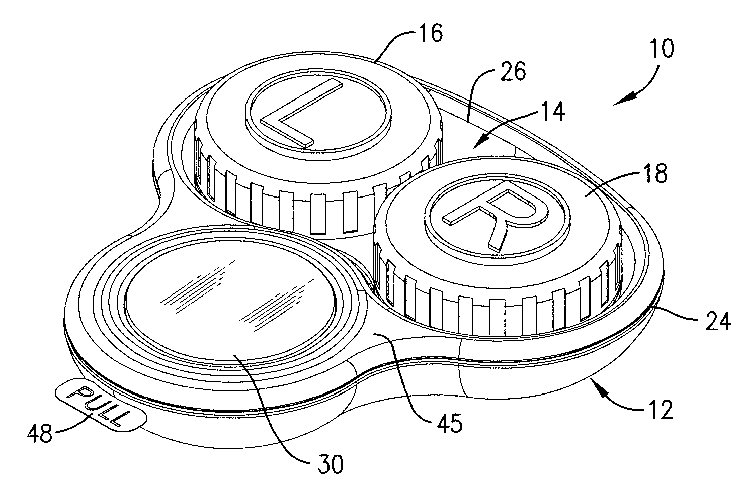
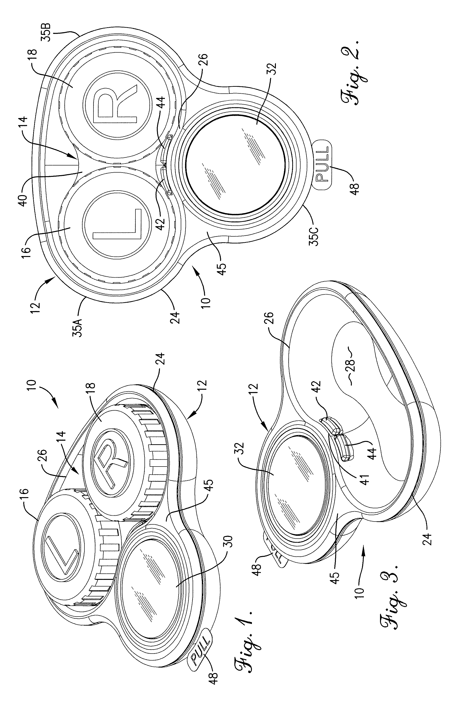
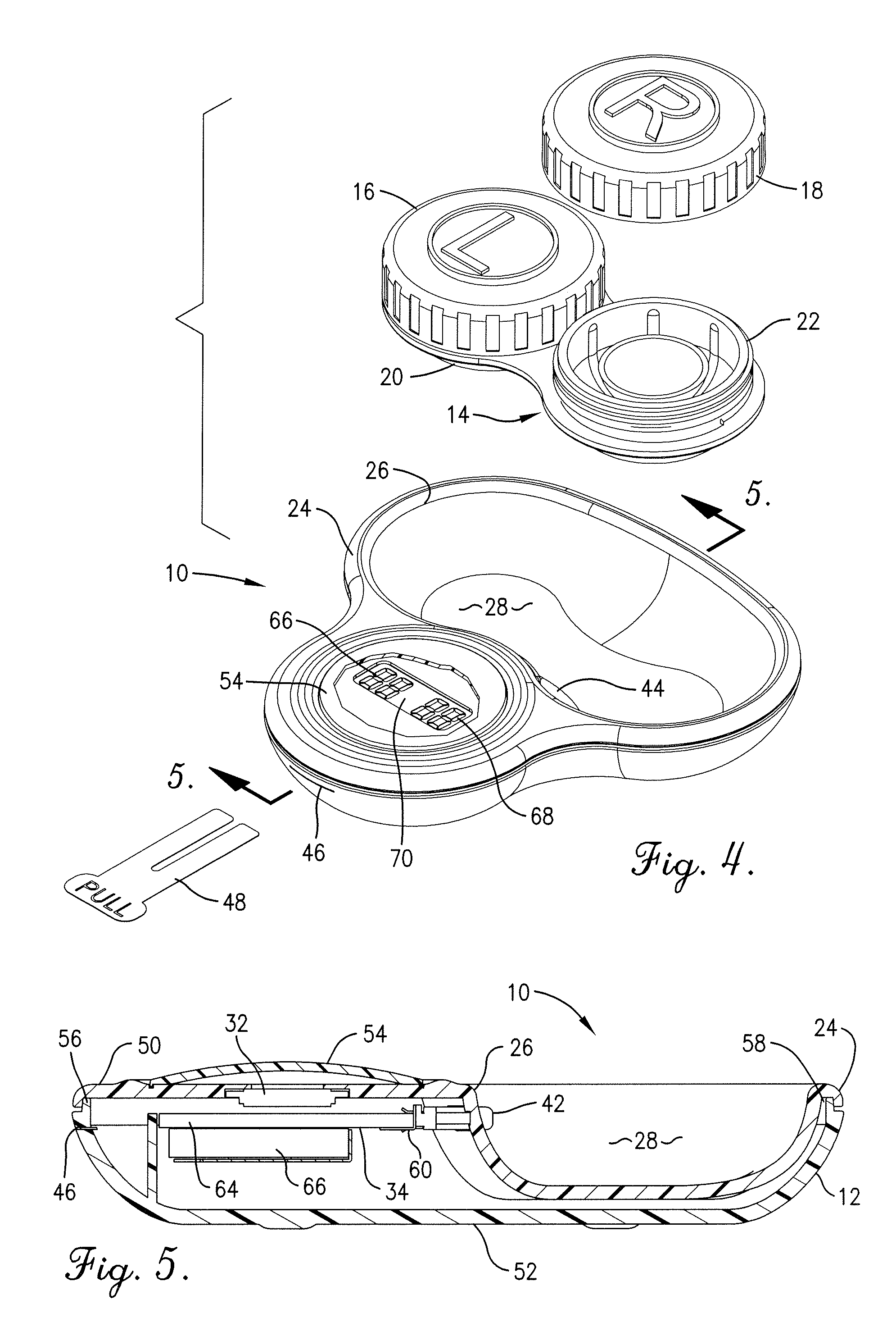
[0021]Referring now to FIGS. 1 and 2 of the drawings, a first embodiment of the countdown timer contact lens case 10 of the present invention broadly includes a main body 12 and a receptacle 14 which includes removable left (L) and right (R) caps 16 and 18 for corresponding left and right lens-receiving chambers 20 and 22. The main body 12 includes a perimeter rim 24 and an inner rim 26 surrounding a receptacle-receiving recess 28, as shown in FIG. 3. The main body 12 further includes a countdown timer 30 which includes a display 32 and a timing circuit 34 as shown in FIG. 5.

[0022]In greater detail, the main body 12 is configured in a three-lobed shape (lobes 35A, 35B and 35C) to removably receive the receptacle 14. As shown in FIGS. 1-4, the recess 28 is configured so as to be complemental in shape to the receptacle 14. For example, the recess 28 as shown in FIGS. 1-5 is configured between lobes 35A and 35B so as to removably receive a receptacle 14. While a number of such receptac...


PUM


Abstract

A countdown timer contact lens case is provided for removably receiving a receptacle and providing independent timing functions for displaying the useful remaining life of a contact lens and for the receptacle for receiving the contact lens when not worn. The countdown timer contact lens case includes a receptacle carried by a main body. The main body includes a timing circuit and a display with first and second indicators corresponding to the respective remaining time for desired use of the lens and for the receptacle. The timer for the lens displays a maximum value which is less than the displayed maximum value of the timer for the receptacle. The timer corresponding to each of the lens and the receptacle can be independent set and reset, and a warning feature is provided to signal the user when the corresponding displayed lens or receptacle value diminishes below a minimum, or decreases to zero.

Description

BACKGROUND OF THE INVENTION[0001]1. Field of the Invention[0002]The present invention concerns a contact lens case which is provided with a resettable timer for allowing the user to monitor the remaining useful period available for the lenses. More particularly, the contact lens case hereof enables the user to also monitor the remaining useful period for the lens receptacle before replacement of the receptacle is recommended.[0003]2. Description of the Prior Art[0004]Contact lenses are well known optical devices used instead of conventional eyeglasses to improve the vision of the wearer and are placed directly on the wearer's eye. To avoid drying of the eye and resulting discomfort arising from wearing of the contact lens for extended periods, particularly during sleep, it is desirable that the contact lens be removed from the eye periodically. During the periods of non-use, the contact lenses need to be stored in a case to facilitate locating them for reuse, avoiding contamination,...

Claims


Application Information

Patent Timeline
Patent Type & Authority Applications(United States)
IPC IPC(8): A45C11/04B65D41/04B65D1/24H05K5/02
CPCA45C11/005
Inventor O'HARA, JOHNPETERSON, CHRISTOPHER L.MARAIA, MICAH L.FEHR, ROBERT G.STONE, MARTIN W.VAN HOOZER, THOMAS H.
Owner OHARA JOHN
Why Eureka
Try Eureka