
Spray nozzle mounting assembly

Inactive Publication Date: 2008-07-31
DEERE & COMPANY & HYPRO
View PDF7 Cites 9 Cited by
  • Summary
  • Abstract
  • Description
  • Claims
  • Application Information

AI Technical Summary

Benefits of technology

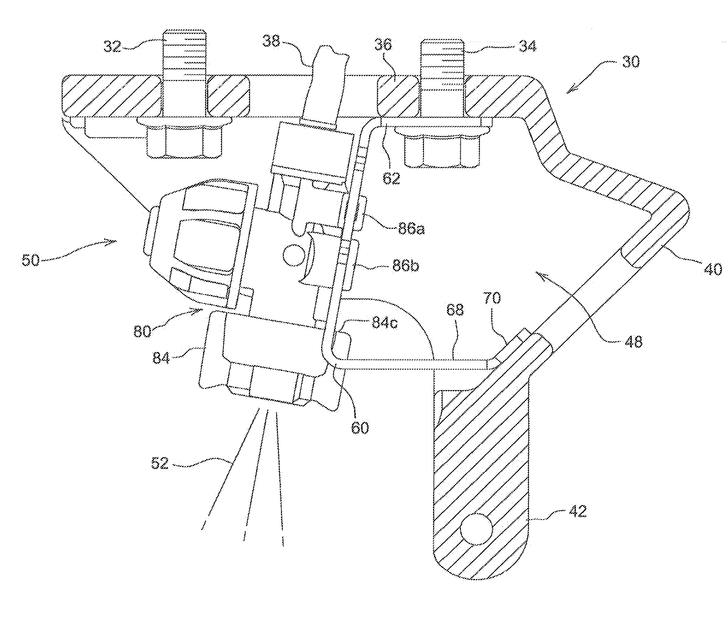
[0003]A nozzle and bracket assembly having a minimal number of parts and particularly useful for mounting on a planter row unit includes a slotted bracket connected by a single bolt to the unit frame. The bracket has extensions that conform to and abut the row unit frame casting to provide additional strength while facilitating easy access to the mounting bolt. A molded plastic nozzle body includes mounting tabs received by the bracket slots. The tabs snap fit into the bracket slots, and the nozzle body is guided into position by the slots. A nozzle cap threaded onto the body adjacent the bracket constrains the body against upward movement to provide a secure nozzle body connection and eliminate or minimize impact damage to the body. The easily replaceable cap contacts the bracket and protects the more costly nozzle body from damage. The assembly is easily installed in the limited space area of the row unit frame and can be conveniently accessed for servicing or changing a nozzle. The entire assembly has few total parts, is extremely compact and is relatively inexpensive to manufacture and install.

Problems solved by technology

Space is extremely limited on the row unit frame, and the mounting of the entire spray assembly can be difficult and time consuming.
The nozzle operates in a relatively harsh environment, and high impact forces can damage the spray assembly.
Repair and replacement of the nozzle are inconvenient because of the limited space and number of mounting components.

Method used


Image

  • Spray nozzle mounting assembly
  • Spray nozzle mounting assembly
  • Spray nozzle mounting assembly

Examples


Embodiment Construction

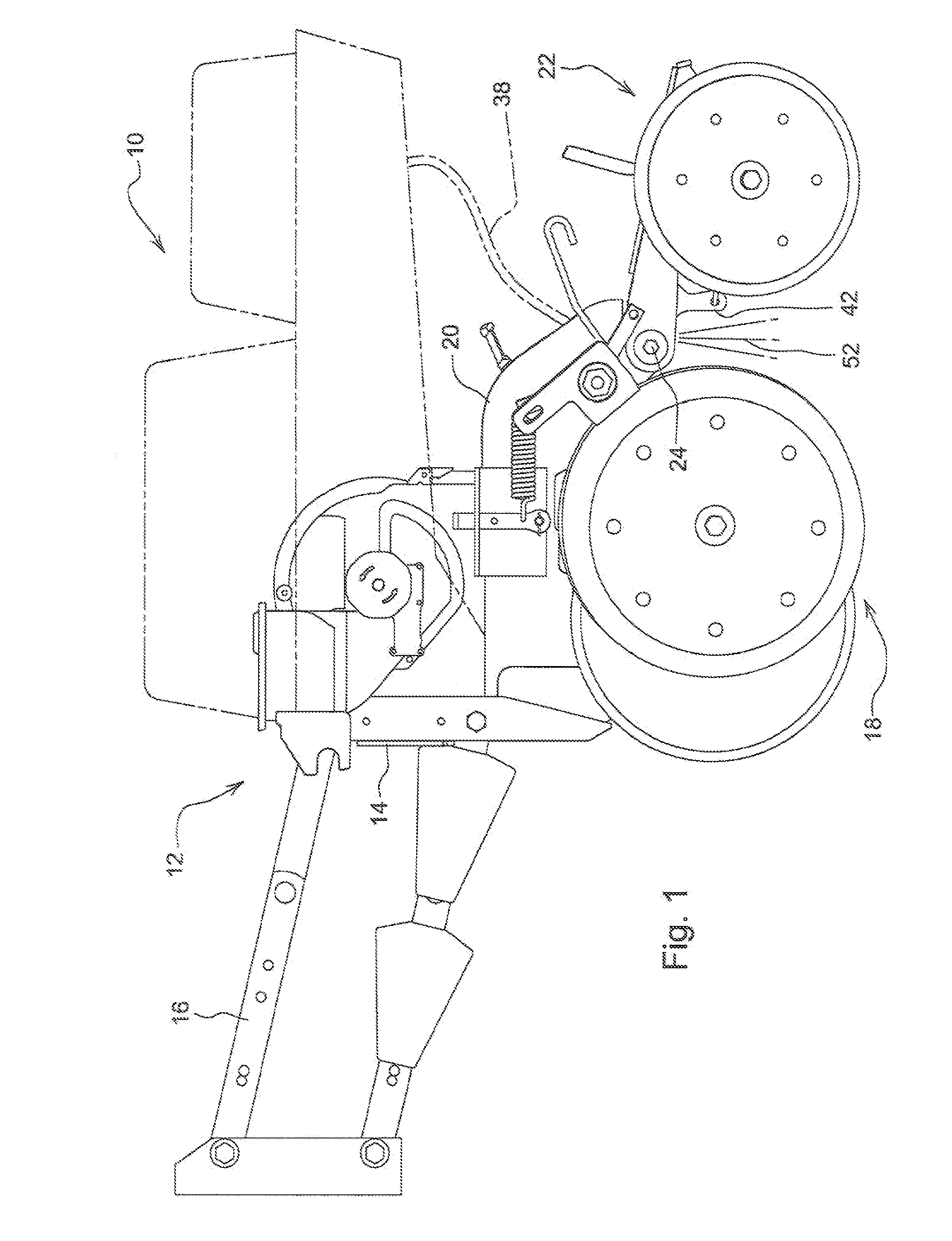
[0012]Referring to FIG. 1 therein is shown a portion of a seeding device 10 adapted for movement over the soil for depositing seed in a furrow and closing the furrow over the seed. As shown, the seeding device 10 is a planter including a row unit 12 having a forward, end 14 connected by a four-bar linkage 18 to a toolbar (not shown). Conventional furrow opening structure 18 with depth gauging is connected to an opener frame 20 and opens a furrow in the ground and deposits material such as seed and fertilizer in the furrow. Trailing press wheel structure 22 supported from the frame 20 at a pivot location 24 firms the soil over the deposited material.

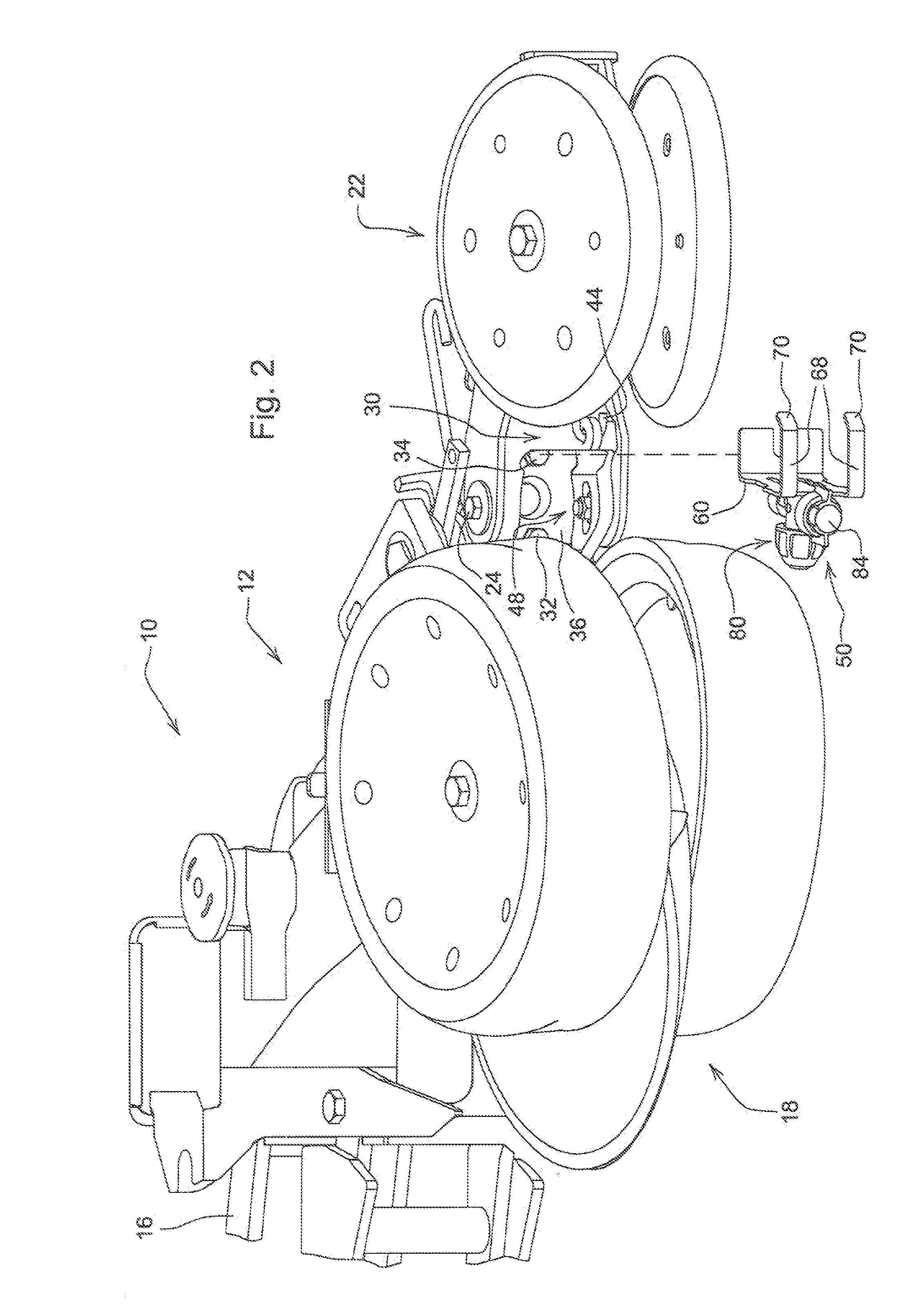
[0013]The opener frame 20 includes a frame casting 30 connected by holts 32 and 34 (FIG. 2) to an underside of the frame 20 immediately rearwardly of the opening structure 18. The casting 30 includes an upper apertured portion 38 receiving, the bolts 32 and 34 and a chemical supply line 38. The casting 30 extends rearwardly and downwardly...


PUM


Abstract

A nozzle and bracket assembly having a minimal number of parts and particularly useful for mounting on a planter row unit includes a slotted bracket connected by a single bolt to the unit frame. A molded plastic nozzle body includes mounting tabs received by the bracket slots. The body snap fits into the bracket slots and is guided into position past locking offsets by the slots. A nozzle cap threaded onto the body constrains the body against upward movement in the slots and transfers harmful impact forces away from the nozzle body.

Description

FIELD OF THE INVENTION[0001]The present invention relates generally to spray nozzle assemblies for agricultural implements and, more specifically, to a nozzle assembly that is particularly useful for attachment on the frame of a seeding device such as a planter row unit.BACKGROUND OF THE INVENTION[0002]Liquid chemicals are often applied in bands or in furrow over an open furrow during planting operations. A typical application arrangement includes a spray nozzle for applying liquid pesticide or other chemical. The nozzle is supported in a bracket that is connected to the frame of a planter row unit by bolts at a location immediately rearwardly of the furrow opening disk. Space is extremely limited on the row unit frame, and the mounting of the entire spray assembly can be difficult and time consuming. The nozzle operates in a relatively harsh environment, and high impact forces can damage the spray assembly. Repair and replacement of the nozzle are inconvenient because of the limite...

Claims


Application Information

Patent Timeline
IPC IPC(8): B05B1/00
CPCA01C7/06B05B15/061A01M7/006A01C23/025B05B15/62
Inventor BEILKE, DANIEL ALLANCARUSO, ROBERT LLOYD
Owner DEERE & COMPANY & HYPRO
Learn More