Adaptor for vehicle mounts

a technology for vehicle mounts and adapters, which is applied in the field of adapters, can solve the problems of unsafe attempts to use mounts for certain lack of adaptability to different types of portable devices, and inability to safely use other devices, etc., and achieves the effect of quick and easy connection to and enhance the adaptability of vehicle mounts

Inactive Publication Date: 2008-07-31
LEE MICHAEL
View PDF22 Cites 53 Cited by
  • Summary
  • Abstract
  • Description
  • Claims
  • Application Information

AI Technical Summary

Benefits of technology

[0008]The adaptor of this invention significantly enhances the adaptability of vehicle mounts to different types and models of portable devices. In the event the existing array of mounting holes in the support plate of the mount does not align with the mounting structure of a particular device, the adaptor of this invention may be quickly and easily connected to such portable device and then secured onto the mount. Further, the adaptor is easily removed from the mount by urging the pin out of engagement with the locking bore in the support plate thus allowing the adaptor to slide out of contact with the support plate and disengage the vehicle mount.

Problems solved by technology

One disadvantage with mounts of the type described above is their lack of adaptability to different types of portable devices, and portable devices sold by different manufacturers.
In either case, the size and location of the mounting holes or bracket(s) are usually designed for one type of device or for the devices of a particular manufacturer, and cannot be safely used with other devices.
It is important the any portable device be securely fastened onto a vehicle mount to avoid it detaching from the mount while the vehicle is in use, and attempts to use mounts for certain types of portable devices can be unsafe.
If a given mount will not work for certain devices, the owner of the vehicle may be forced to purchase different mounts for his or her portable devices and / or be restricted as to which devices may be transported on the vehicle with one particular mount.

Method used


Image

  • Adaptor for vehicle mounts
  • Adaptor for vehicle mounts
  • Adaptor for vehicle mounts

Examples


Embodiment Construction

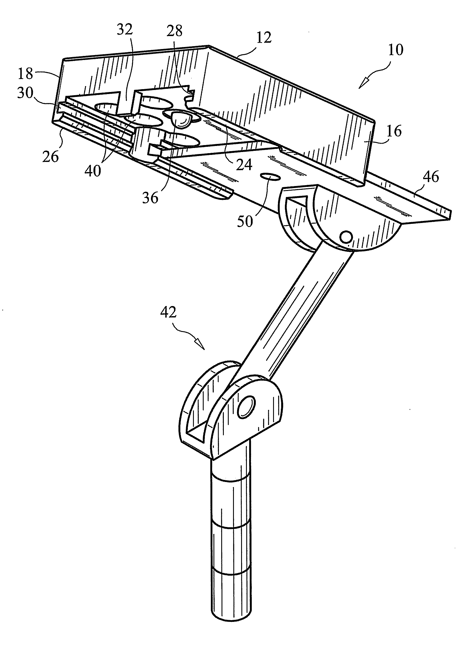
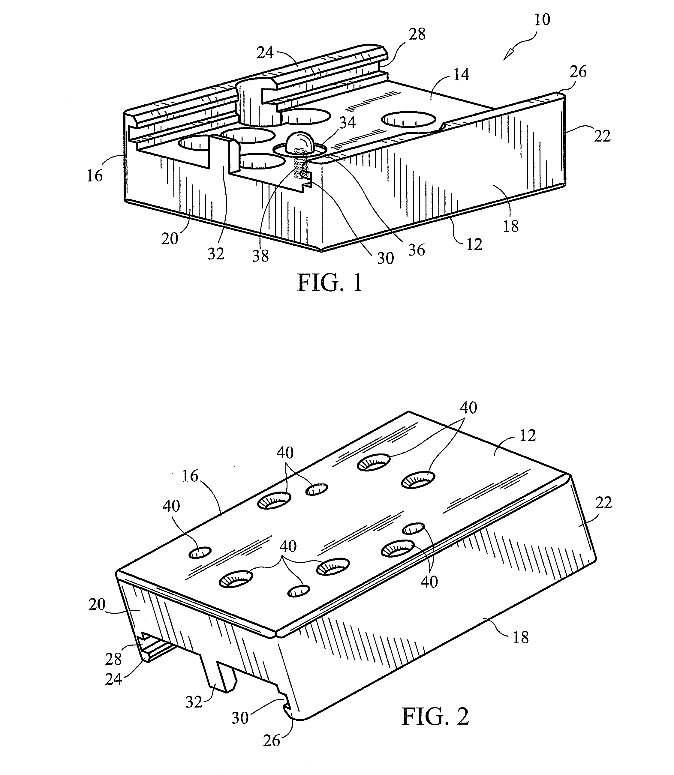
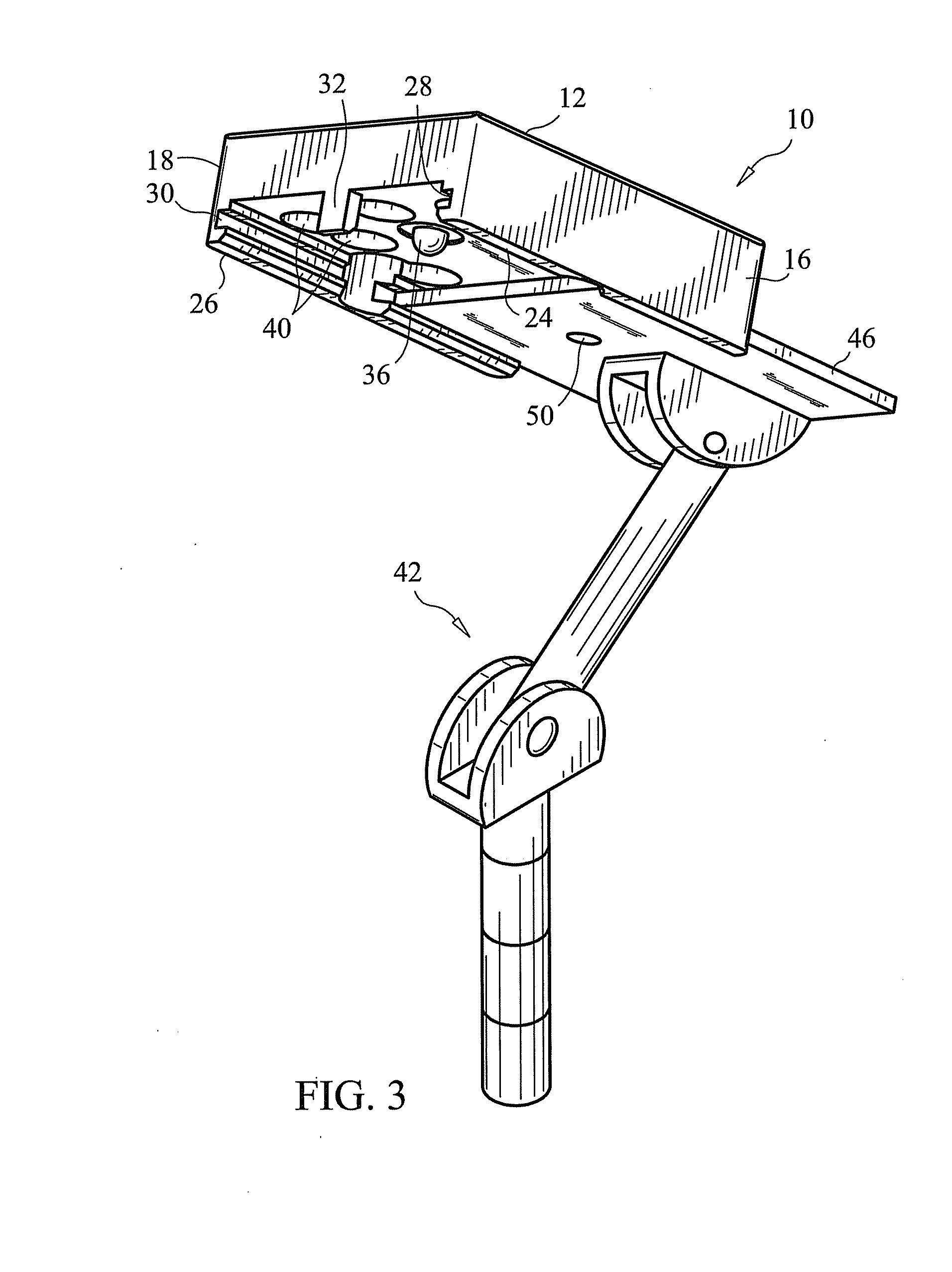
[0014]Referring now to the Figs., the adaptor 10 of this invention comprises a top wall 12, a bottom wall 14, opposed side walls 16 and 18, and, opposed end walls 20 and 22. The side wall 16 has a lower portion 24 that projects outwardly from the bottom wall 14, and the side wall 18 has a similar lower portion 26. The lower portions 24 and 26 are formed with channels 28 and 30, respectively, each of which extends between the end walls 20, 22. A stop 32 extends from the bottom wall 14 toward the top wall 12 generally flush with the end wall 20. For purposes of the present discussion, the terms “top,”“bottom,”“upper,”“lower” and the like refer to the orientation of the actuator 10 as viewed in FIG. 2.

[0015]In the presently preferred embodiment, a bore 34 is formed in the bottom wall 14 within which a pin 36 is axially movable, i.e. in a direction toward and away from the top wall 12. The pin 36 is connected to one end of a coil spring 38 whose opposite end mounts to the underside of t...


PUM


Abstract

An adaptor for securing portable devices to mounts used in vehicles such as motorcycles comprises a top wall, a bottom wall, opposed end walls and opposed side walls each having a lower portion that projects outwardly from the bottom wall and is formed with a channel extending from one end wall to the other. A support plate of the vehicle mount slides into these channels, and a spring-biased pin carried by the bottom wall of the adaptor secures the adaptor in place onto the vehicle mount by extending into a locking bore formed in the support plate of such mount.

Description

FIELD OF THE INVENTION[0001]This invention relates to vehicle mounts, and, more particularly, to an adaptor that allows a number of different portable devices to be mounted to the same vehicle mount.BACKGROUND OF THE INVENTION[0002]Motorcycles, snowmobiles, personal watercraft, all-terrain vehicles and the like have become increasingly popular in recent years. Owners of these vehicles have demanded increased accessibility and improved ease of use for accessory items such as global positioning devices (GPS), radar detectors, toll transponders, cell phones, radios, cameras, change holders, garage door openers, personal digital assistants (PDA) and other portable devices. In response to this demand, a variety of mounts have been developed for securing portable devices in an easily accessible location on such vehicles, including control mounts, stem mounts, handlebar mounts, mirror mounts, fairing mounts, specialty mounts and others.[0003]Mounts of the type noted above are secured to di...

Claims


Application Information

Patent Timeline
Patent Type & Authority Applications(United States)
IPC IPC(8): F16M11/00
CPCB60R11/00B60R11/02B60R2011/0003B62J11/00B60R2011/004B60R2011/0059B60R2011/0089B60R2011/001
Inventor LEE, MICHAEL
Owner LEE MICHAEL
Why Eureka
Try Eureka