Truss assembly table with automatic jigging

a technology jig setting system, which is applied in the direction of manufacturing tools, work holders, metal-working machine components, etc., can solve the problems of affecting the reliability of jig system use, affecting the safety of truss assembly table,

Active Publication Date: 2008-07-31
ILLINOIS TOOL WORKS INC
View PDF32 Cites 16 Cited by
  • Summary
  • Abstract
  • Description
  • Claims
  • Application Information

AI Technical Summary

Benefits of technology

[0017]A automatic jigging assembly for use on a truss assembly table is presented. A threaded rod turns under the influence of a motor which is controlled by a motion control system. The threaded rod causes a puck to move along a slot in the truss table to a position which will define the perimeter of a truss. The puck is attached to the carriage which is positioned under the table top. A threaded insert may be used between the carriage and the threaded rod. For maintenance purposes, this insert should be made from a material that provides permanent self lubrication and long wear without the addition of dry or wet lubricants that can attract and trap dirt, dust, and debris.

Problems solved by technology

While in concept these systems can save time otherwise needed to measure, move and secure the stops on the table, there have been problems that have cropped up with these systems that make them less time saving and reliable as they could be for optimum efficiency.
The environment in which the jig systems are used is filled with debris and dust.
As each puck is typically mounted on a screw-threaded rod that is positioned below the puck in the slot, the debris often falls onto the rod.
Since the rod rotates to move the puck, a rod caked with debris can hamper and even prevent movement of the puck along the rod.
Further complicating this situation is the fact that the screw-threaded rods typically are covered with some type of lubricant to facilitate movement of the puck along the rod, and this often sticky lubricant holds the debris on the surface of the rod.
The encrusted rod can carry the debris into the cooperating parts of the system, and cause additional friction and failure.
Still further exacerbating this problem in the known systems is the placement of the rod in a channel located below the slot with a closed bottom that holds the debris in close proximity to the rod, so that infrequent clearing of the channels can bring debris in contact with the rods from the bottom, as well as from the top as debris falls from the table surface.
At this length, the threaded rod will sag under its own weight and, when turned at high revolutions per minute, will whip and gyrate violently unless it is properly constrained.
None of the components of the system will allow the accumulation of dirt and debris.
This abuse comes primarily from lumber that is being tossed onto the surface of the table and moved into position for truss assembly.
Thus, while the known systems for automatically positioning the pucks on the jig assembly table are an improvement over jig systems requiring manual positioning of the stops, there are significant problems that have arisen with the use of automatic systems.

Method used


Image

  • Truss assembly table with automatic jigging
  • Truss assembly table with automatic jigging
  • Truss assembly table with automatic jigging

Examples


Embodiment Construction

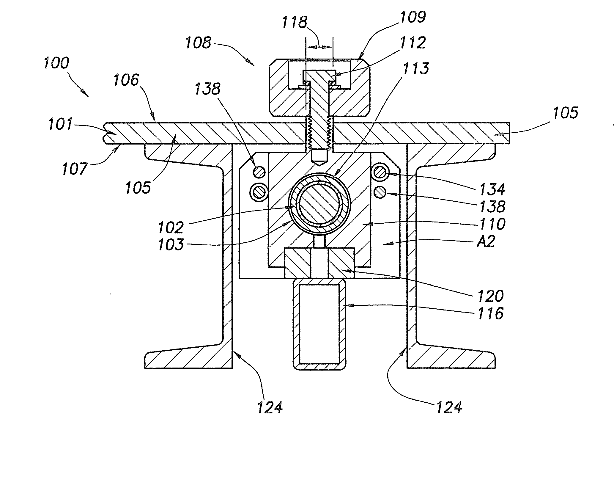
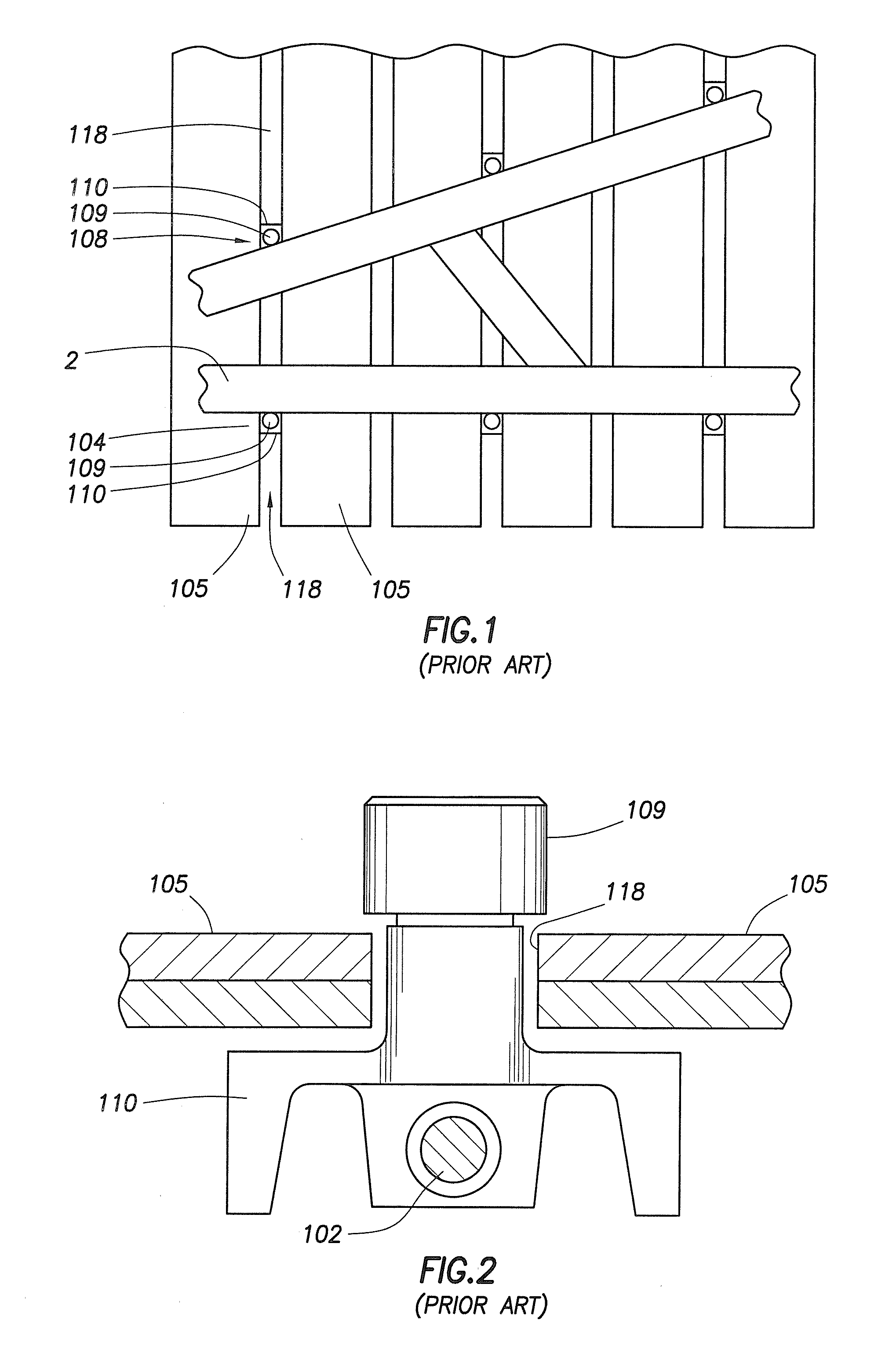
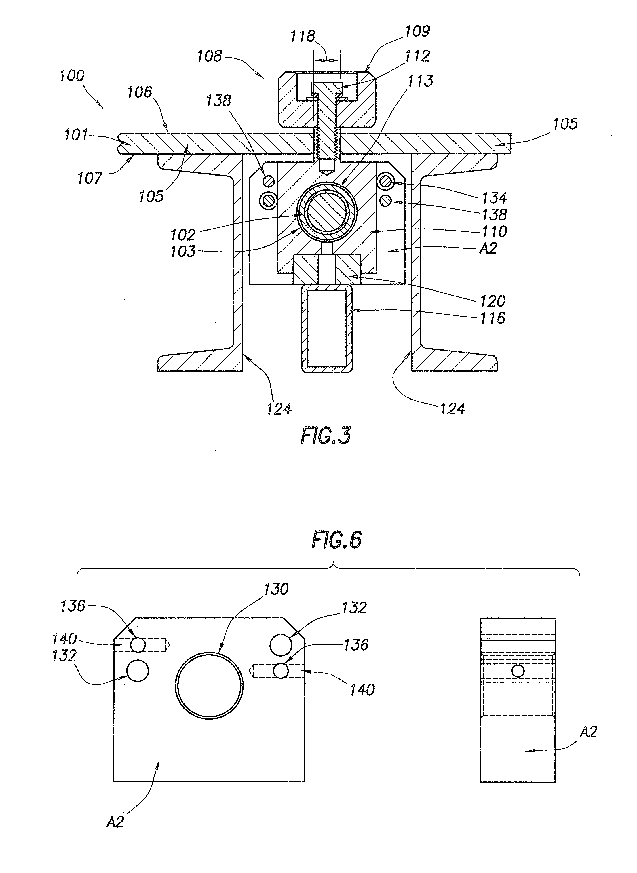
[0029]FIG. 1 illustrates the prior art truss jig positioning system 100 employed on a table 101 that has and defines a support plane 104 on which work pieces or building elements, such as wood boards 2 or other building materials, are supported in proper position for forming a structure such as a support truss for a roof of a building. The table 101 may comprise a plurality of segments 105 that have upper surfaces 106 that substantially lie in and define the support plane or work surface 104 of the table 101. The upper surface of each of the table segments 105 may be substantially planar, and a plane of the segments may be oriented substantially horizontally. The table segments 105 also have lower surfaces 107.

[0030]The segments 105 of the table are separated by openings or jigging slots 118 which extend laterally across the table 101 and preferably extend substantially parallel to each other. Each of the slots 118 may extend substantially perpendicularly to the length of the table ...


PUM

PropertyMeasurementUnit
lengthaaaaaaaaaa
areasaaaaaaaaaa
rotational movementaaaaaaaaaa

Abstract

A jig positioning system for use on a truss assembly table. The puck assembly 108 has a puck 109 positioned at least partially above the table top 105 with the puck 109 connected to a carriage 110 positioned at least partially below the table top. The puck assembly 108 moves along slots 118 in the table top 105. A threaded rod 102 extends through a threaded passageway 103 in the carriage 110, so, when the threaded rod rotates, the puck assembly moves along a corresponding slot in the table. A rod support member 116 extends along the length of the threaded rod 102 and is positioned below the threaded rod 102, the support member 116 contacting the carriage and, thereby, preventing the threaded rod from excessive sagging. A debris path is provided along both sides of the support member 116.

Description

CROSS REFERENCE TO RELATED APPLICATION[0001]This application claims priority of provisional Ser. No. 60 / 887,096, filed Jan. 29, 2007STATEMENT REGARDING FEDERALLY SPONSORED RESEARCH OR DEVELOPMENT[0002]Not applicableREFERENCE TO MICROFICHE APPENDIX[0003]Not applicableTECHNICAL FIELD[0004]The present invention relates to automatic jig setting systems for positioning jig pucks on a truss assembly table. More particularly, the invention relates to such a system having a threaded rod for positioning the jig pucks and providing adequate support for the threaded rod.BACKGROUND OF THE INVENTION[0005]Jig systems have been used to hold building elements, such as wood boards, in proper position while the building elements are attached to each other to construct a roof support truss. Known jig systems typically employ a horizontal surface (such as a table) for resting the building elements thereon and a plurality of adjustable stops for indicating the proper positions of the building elements i...

Claims


Application Information

Patent Timeline
Patent Type & Authority Applications(United States)
IPC IPC(8): B25B11/02
CPCY10T29/5397B25H1/10
Inventor MCADOO, DAVID L.FINDLEY, RONALD E.CEURTER, JEFFREYBRADLEY, NEILL
Owner ILLINOIS TOOL WORKS INC
Why Eureka
Try Eureka