Plane circular polarization antenna and electronic apparatus

Active Publication Date: 2008-07-31
CASIO COMPUTER CO LTD
View PDF11 Cites 55 Cited by
  • Summary
  • Abstract
  • Description
  • Claims
  • Application Information

AI Technical Summary

Benefits of technology

[0011]An object of the present invention is to provide a plane circular polarization antenna t

Problems solved by technology

Thus, when the conventional film antenna is applied to mobile communication (in particular, a portable communication apparatus such as a handy terminal), the mobile communication may become unstable and may be disrupted depending on orientation of the antenna.
The conventional film type inverted F plane antenna which radiates vertical and horizontal polarization cannot make phase difference between elements, therefore, it is not possible to radiate circular polarization.
The conventional film antenna which produces circular polarization using the loop antenna is large in sh

Method used


Image

  • Plane circular polarization antenna and electronic apparatus
  • Plane circular polarization antenna and electronic apparatus
  • Plane circular polarization antenna and electronic apparatus

Examples


first modification

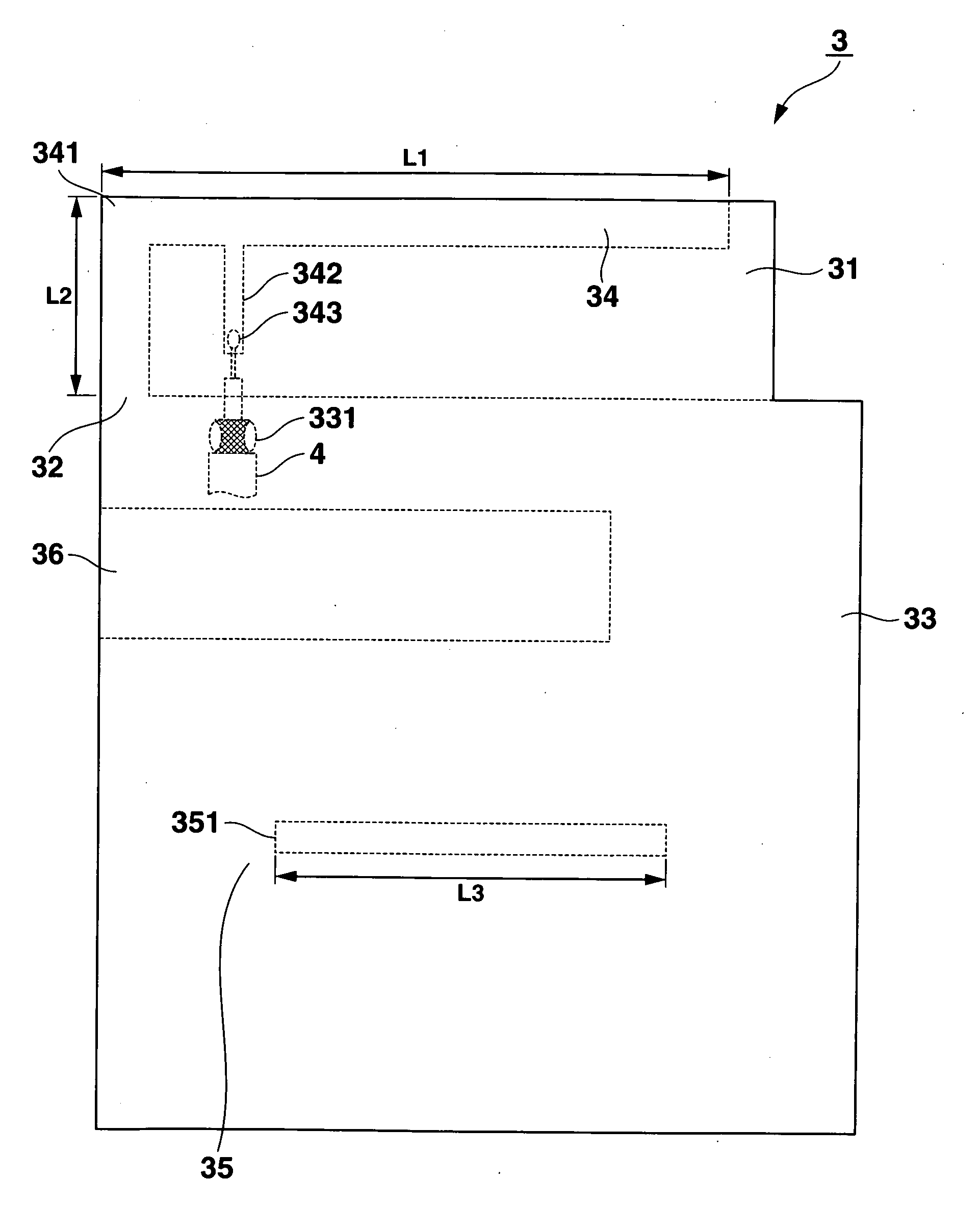
[0087]A first modification of the above embodiment will be described with reference to FIG. 10. FIG. 10 is a plan view showing planar configuration of a plane circular polarization antenna 3A.

[0088]As shown in FIG. 10, the plane circular polarization antenna 3A of the present modification includes a ground short portion 37 instead of the ground short portion 36 of the above plane circular polarization antenna 3. The conductive gasket (not shown) of the present modification is in the shape of a rectangular cylinder, and the ground short portion 37 is correspondingly in the shape of a cross section of a rectangular cylinder.

[0089]According to the plane circular polarization antenna 3A of the present variation, effects similar to the above-described embodiment is realized and weight of the ground short portion 37 can be saved.

second modification

[0090]A second modification of the above embodiment will be described with reference to FIGS. 11A to 11C. FIG. 11A is a plan view showing a part of planar configuration of a plane circular polarization antenna 3B. FIG. 11B is a plan view showing a part of planar configuration of a plane circular polarization antenna 3C. FIG. 11C is a plan view showing a part of planar configuration of a plane circular polarization antenna 3D.

[0091]The plane circular polarization antennas 3B, 3C, and 3D of the present modification are obtained by changing the feeding position of the coaxial cable 4 in the plane circular polarization antenna 3 of the above embodiment. In FIGS. 11A to 11C, the base film 31 is omitted to simplify the figures.

[0092]As shown in FIG. 11A, the plane circular polarization antenna 3B of the present modification includes an inverted F antenna 34B instead of the inverted F antenna 34 of the plane circular polarization antenna 3 described in the above embodiment. The inverted F ...

third modification

[0096]A third modification of the above embodiment will be described with reference to FIGS. 12A to 12C. FIG. 12A is a plan view showing schematic planar configuration of a plane circular polarization antenna 3E. FIG. 12B is a plan view showing schematic planar configuration of a plane circular polarization antenna 3F. FIG. 12C is a plan view showing schematic planar configuration of a plane circular polarization antenna 3G.

[0097]The plane circular polarization antennas 3E to 3G of the present modification are obtained by changing the shape of the slot antenna 35 of the plane circular polarization antenna 3 described in the above embodiment. In FIGS. 12A to 12C, the base film 31 is omitted to simplify the figures.

[0098]As shown in FIG. 12A, the plane circular polarization antenna 3E of the present modification includes a slot antenna 35E instead of the slot antenna 35 of the plane circular polarization antenna 3 described in the above embodiment. The slot antenna 35E comprises a slo...


PUM


Abstract

According to an embodiment, a plane circular polarization antenna comprises a flat insulating substrate and a conductor provided on the flat insulating substrate. The conductor comprises an inverted F antenna including a feeding point, a ground portion, the ground portion including a slot antenna including a slot, and a short-circuiting portion provided in a part of an area between the inverted F antenna and the slot antenna.

Description

CROSS-REFERENCE TO RELATED APPLICATIONS[0001]This application is based upon and claims the benefit of priority from prior Japanese Patent Application No. 2007-021301, filed Jan. 31, 2007, the entire contents of which are incorporated herein by reference.BACKGROUND OF THE INVENTION[0002]1. Field of the Invention[0003]The present invention relates to a plane circular polarization antenna and an electronic apparatus.[0004]2. Description of the Related Art[0005]Conventionally, antennas of portable terminals such as a portable phone and a personal digital assistant (PDA) for wireless communication have been decreased in size. For example, a film antenna is proposed which has an antenna pattern on a planar film and radiates single polarization (for example, Japanese Patent No. 3656610 and Japanese Patent No. 3622959). Also, a film antenna which radiates vertical polarization and horizontal polarization simultaneously is proposed (for example, Japanese Patent No. 3830358). The above film a...

Claims


Application Information

Patent Timeline
IPC IPC(8): H01Q9/04H01Q13/10
CPCH01Q1/243H01Q13/10H01Q9/42H01Q9/0421
Inventor YAGI, SHIGERU
Owner CASIO COMPUTER CO LTD
Why Eureka
Try Eureka