Image capture apparatus

Inactive Publication Date: 2008-07-31
SONY CORP
View PDF4 Cites 9 Cited by
  • Summary
  • Abstract
  • Description
  • Claims
  • Application Information

AI Technical Summary

Benefits of technology

[0008]In view of the above, it would be desirable to provide an image capture apparatus advantageous for improving operability in a connector insertion / removal operation.
[0010]According to the embodiment of the present invention, the insertion / removal opening of the connector can easily be opened and closed by the cover by operating the operation member. This is advantageous to improve the operability.
[0011]Further, when the cover is positioned in the opened position, the cover is stored in the housing body. Consequently, the cover does not hinder the insertion or removal operation for connection or disconnection between the connector on the image capture apparatus and a cable connector. This is advantageous to improve the operability in the event of the insertion or removal operation for connection or disconnection between the connectors.
[0012]Further, when the cover is positioned in the closed position, the cover and the housing body form an integral exterior. On the other hand, when the cover is positioned in the opened position, the cover is not situated in a loose or dangling state in the outside of the housing body. This is advantageous to improve the design function.

Problems solved by technology

However, the operation for engagement or disengagement of the cover with the cover-receiving portion(s) of the connector(s) is intricate.
Further, such the state of the cover is disadvantageous in the exterior of the apparatus.

Method used


Image

  • Image capture apparatus
  • Image capture apparatus
  • Image capture apparatus

Examples


Embodiment Construction

[0044]An embodiment of the present invention will be described below with reference to the accompanying drawings.

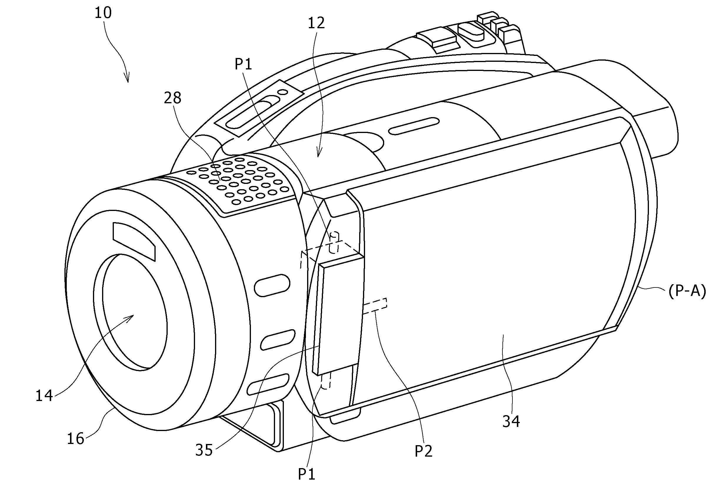
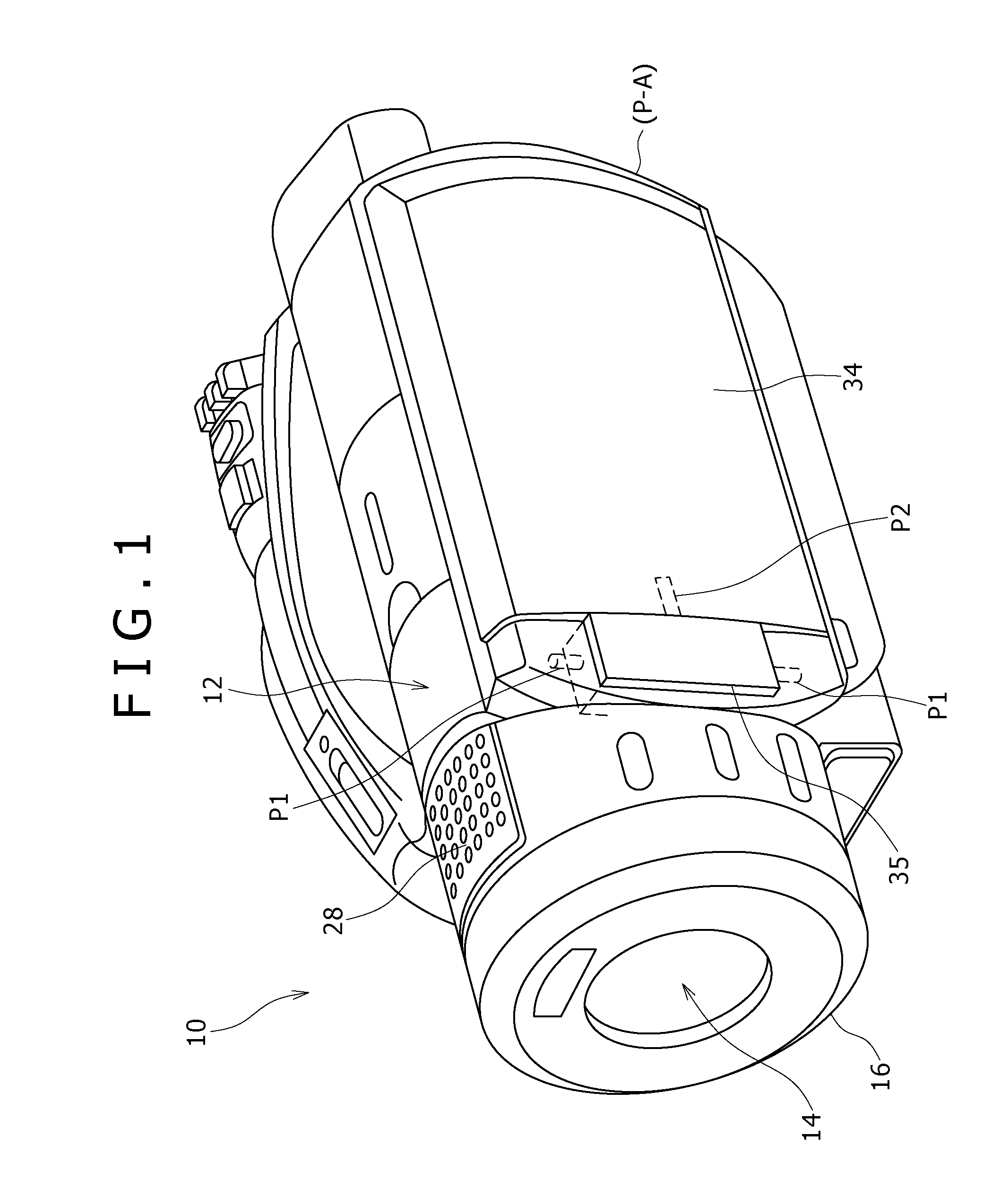
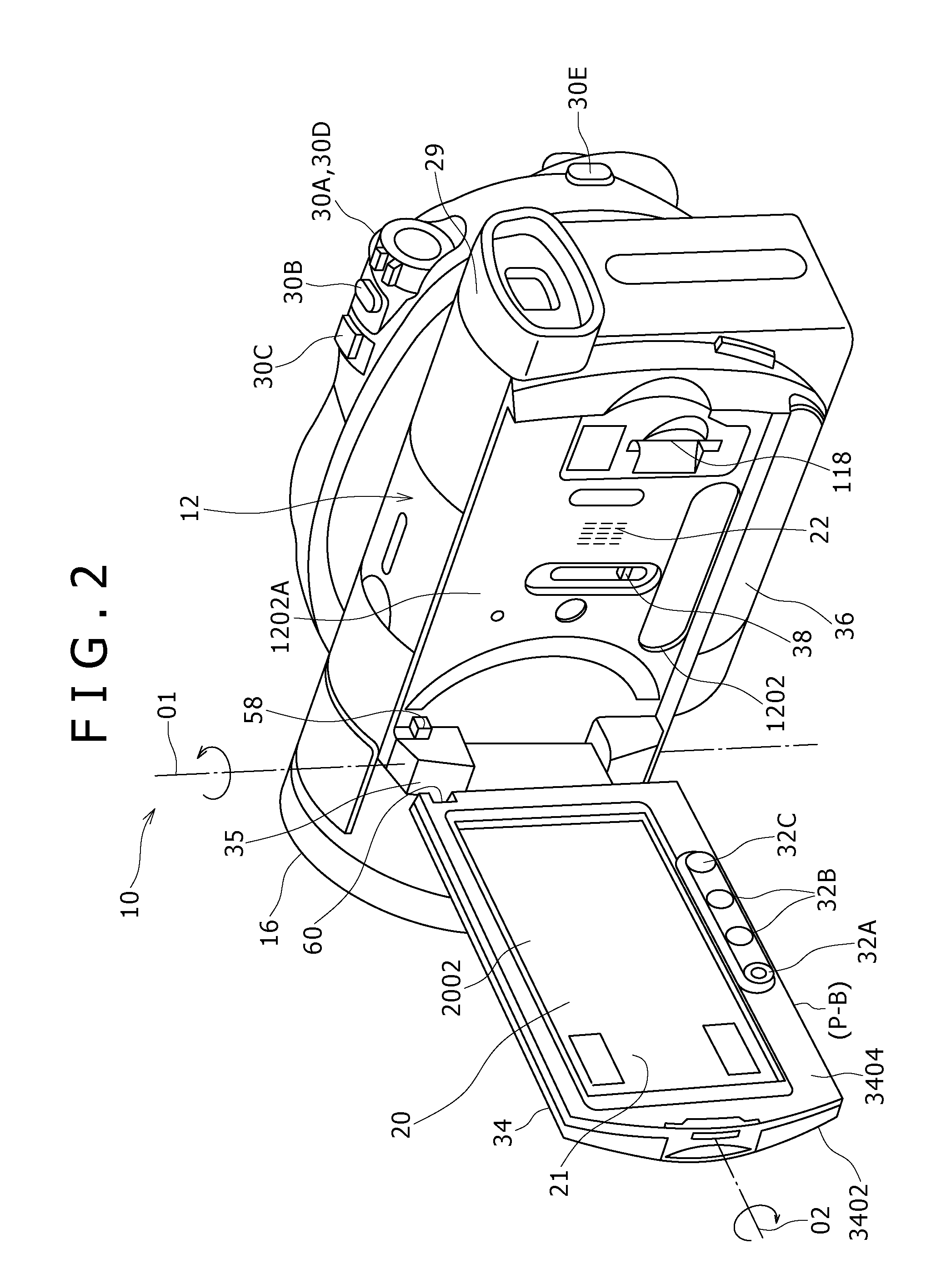
[0045]FIGS. 1 to 3, respectively, are perspective views showing the configuration of an image capture apparatus 10 of the embodiment. FIG. 5 is a left side view of the image capture apparatus 10 of the embodiment. FIGS. 6 to 8, respectively, are views taken from directions indicated by the arrows A to C of FIG. 5; and FIG. 9 is a view taken from a direction indicated by the arrow D of FIG. 6.

[0046]With reference to FIGS. 1 to 3 and 5 to 9, the image capture apparatus 10 of the present embodiment is a video camera that performs image capture in accordance with the HDTV (high-definition television) scheme, i.e., HDV standards.

[0047]A housing body 12 constituting the exterior of the image capture apparatus 10 has a length in a frontward-and-rearward direction and a height in an upward-downward direction (or, vertical direction) that are larger than a width in a left-and-righ...


PUM


Abstract

An image capture apparatus includes a housing body, an image capture optical system, an image capture device, a connector, a cover, and an operation member. The display panel is provided to the housing body to be pivotable between a usage position where a display surface of the display panel is visible and a storage position where the display surface of the display panel is in contact with a surface of the housing body. The cover opens or closes the insertion / removal opening by extending or retracting on the insertion / removal opening from an interior of the housing body. The operation member is provided to the housing body, and is operated to move the cover along a direction of opening or closing the insertion / removal opening, the operation member being provided to the housing body.

Description

[0001]The present invention contains subject matter related to Japanese Patent Application JP 2006-194100 filed in the Japanese Patent Office on Jul. 14, 2006, the entire contents of which being incorporated herein by reference.BACKGROUND OF THE INVENTION[0002]1. Field of the Invention[0003]The present invention relates to an image capture apparatus.[0004]2. Description of the Related Art[0005]In many cases, image capture apparatuses, such as video cameras, have electrical connectors (simply “connectors,” hereinbelow) for connecting cables to external devices, such as a television device and a computer, for communication of signals, such as audio and video signals.[0006]According to a previously proposed technique (see Patent Publication 1 (Japanese Unexamined Patent Application Publication No. 2005-184669)), an apparatus such as described above has a cover for protecting connectors on two sides from foreign matter such as dust. As seen from the publication, the cover is engageable ...

Claims


Application Information

Patent Timeline
IPC IPC(8): H04N5/225G03B17/02
CPCH04N5/2251G03B17/02H04N23/531
Inventor MITO, TOMOYUKITAKAHASHI, NOBUTATSUISAWA, HIDETOSHI
Owner SONY CORP
Why Eureka
Try Eureka