Apparatus for checking concentricity between lens barrel and barrel holder

Inactive Publication Date: 2008-07-31
HON HAI PRECISION IND CO LTD
View PDF5 Cites 6 Cited by
  • Summary
  • Abstract
  • Description
  • Claims
  • Application Information

AI Technical Summary

Benefits of technology

[0010]Advantages and novel features will become more apparent from the following detailed description of the present apparatu

Problems solved by technology

However, rotating the lens barrel by hand is in

Method used


Image

  • Apparatus for checking concentricity between lens barrel and barrel holder
  • Apparatus for checking concentricity between lens barrel and barrel holder
  • Apparatus for checking concentricity between lens barrel and barrel holder

Examples


Embodiment Construction

[0018]Reference will now be made to the drawings to describe present embodiments of the present apparatus for checking concentricity between the lens barrel and the barrel holder.

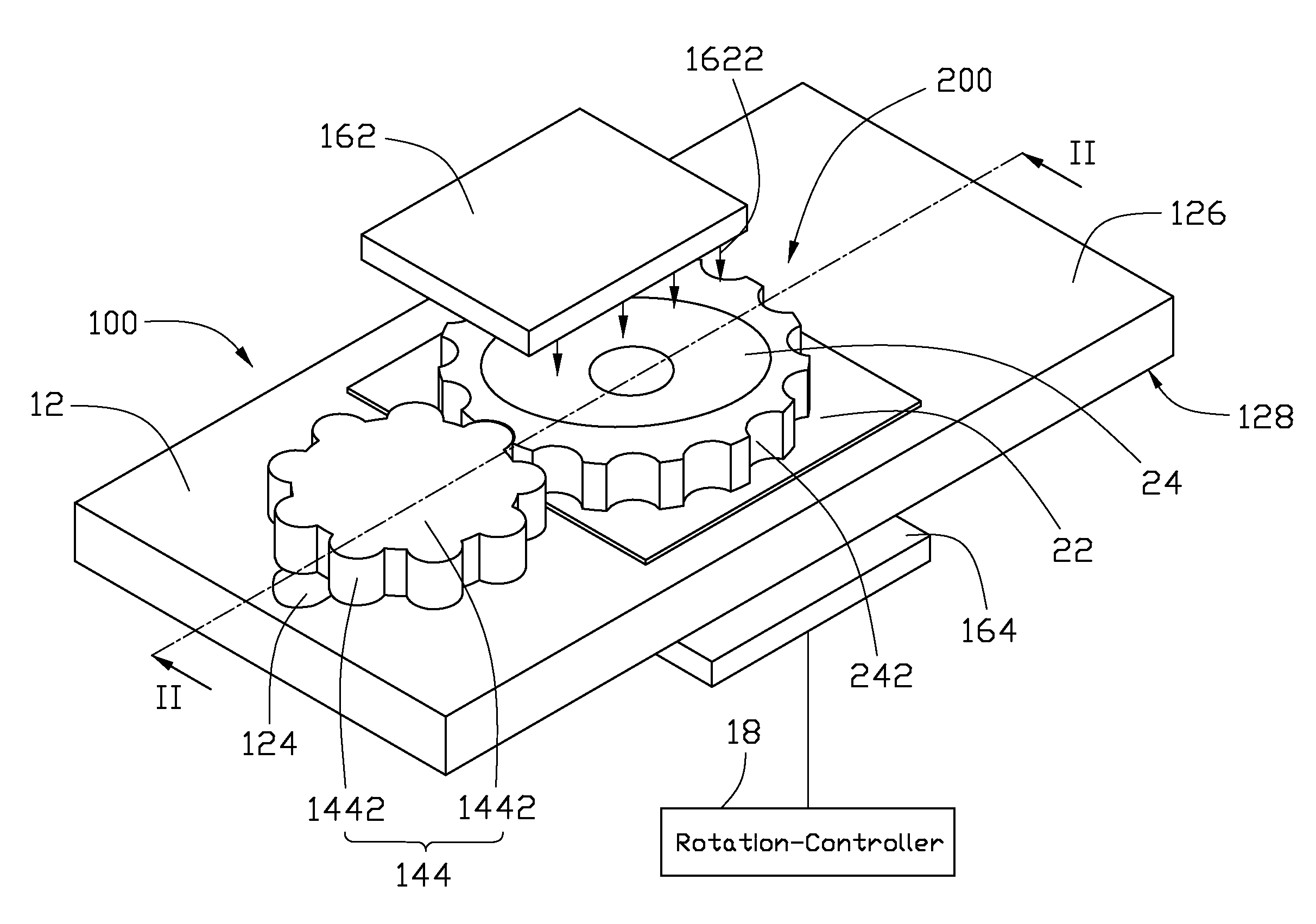
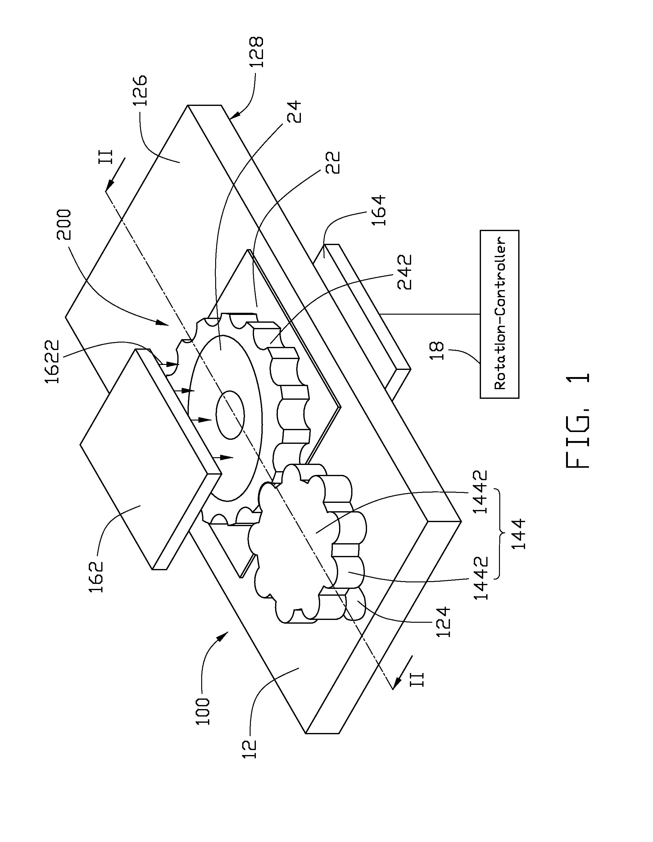
[0019]Referring to FIGS. 1 to 2, a concentricity checking apparatus 100 and an optical module 200 is illustrate in accordance with a first present embodiment. The optical module 200 includes a barrel holder 22, a lens barrel 24 and a lens group 26. The lens group 26 is coaxially received in the lens barrel 24. The lens barrel 24 is rotatably engaged in the barrel holder 22 through thread grooves. A plurality of cutouts 242 is defined in a periphery of the lens barrel 24. Preferably, a distance between each two adjacent cutouts 242 is equal. The lens group 26 may include one or more lenses. In the present embodiment, the lens group 24 has one lens. An image side 202 and an object side 204 are defined at two opposite sides of the optical module 200. The concentricity checking apparatus 100 includes a platform...


PUM


Abstract

An apparatus for checking concentricity between a barrel holder and a lens barrel rotatably engaging with the barrel holder is provided. The lens barrel includes at least one lens coaxially received therein. The apparatus includes a barrel holder retaining member, a rotating member, a driving unit, a light source, and an image sensor. The barrel holder retaining member is used for fixedly retaining the barrel holder in position. The rotating member is structured for meshing with the lens barrel. The driving unit is used for driving the rotating member to rotate, thereby rotates the lens barrel. The light source is configured for emitting light toward a first end of the lens barrel. The image sensor is arranged to face toward an opposite second end of the lens barrel. The image sensor is configured for sensing the light emitted from the light source.

Description

BACKGROUND [0001]1. Field of the Invention[0002]The present invention relates to testing apparatuses, more particularly to an apparatus for checking concentricity between the lens barrel and the barrel holder.[0003]2. Description of Related Art[0004]With the ongoing development of microcircuitry and multimedia technology, digital cameras are now in widespread use. High-end portable electronic devices, such as mobile phones and PDAs (Personal Digital Assistants), are being developed to be increasingly multi-functional. Many of these portable electronic devices are now equipped with a digital camera. The camera generally includes an optical module.[0005]Optical modules used for digital camera modules typically include a lens barrel, a lens module, a spacer, a filter, and a lens holder. The lens module, the spacer, and the filter are engagingly received in the lens barrel one on top of one another, in the order written. Generally, the lens barrel is mounted in the lens holder through t...

Claims


Application Information

Patent Timeline
IPC IPC(8): G01B11/27
CPCG01B11/27G03B43/00G02B27/62G02B13/001
Inventor YEN, SHIH-CHIEH
Owner HON HAI PRECISION IND CO LTD
Why Eureka
Try Eureka