Light Field Microscope With Lenslet Array

a technology of light field microscope and lenslet array, which is applied in the field of three-dimensional light field microscope, can solve the problems of inconvenient operation, additional mechanical parts add considerable complexity to the microscope and operation, and the robust way is extremely difficult, so as to avoid mechanical complications, reduce the loss of pixels, and improve the effect of quality

Active Publication Date: 2008-07-31
ADOBE SYST INC
View PDF5 Cites 89 Cited by
  • Summary
  • Abstract
  • Description
  • Claims
  • Application Information

AI Technical Summary

Benefits of technology

[0015]The size of the lenses used in the lenslet array make it feasible to correct the lenses for aberrations. Locating the lenslet array at or near the objective lens avoids mechanical complications; for example, no additional high-precision turret to hold the lenslet array is required.
[0016]The light field produced by the lenslet array is not transposed. A light field microscope with the lenslet array captures, for example, 100 real images as opposed to, for example, 55,000 angular images captured by a microlens array located at the image plane. As a result, each image captured using the lenslet array is much larger than an individual image captured using a microlens array located at the image plane, which means that there are far fewer wasted boundary pixels as a percentage of the total number of pixels. Thus, the same sensor can be used to capture higher resolution images, with much less loss of pixels, than can be captured with a microscope using a microlens array located at the image plane.

Problems solved by technology

Each angular image is not a complete image, and each image taken by itself is meaningless and not particularly useful.
This additional mechanical part adds considerable complexity to the microscope and operation thereof.
Switching from one microlens array 110 to another with the above precision and in a robust way is extremely difficult as a mechanical problem, adding to the expense of the second turret.
Such an array of microlenses is expensive and difficult to manufacture.
In addition, correction for aberration would be extremely difficult, considering the size and the number of microlenses that are used.
In addition, there may be many unused pixels on the sensor not illuminated by a microlens.
Thus, as much as 50%, or more, of the sensor's pixels may be wasted.
Further, the smaller the image size, the higher a percentage of pixels will be lost.

Method used


Image

  • Light Field Microscope With Lenslet Array
  • Light Field Microscope With Lenslet Array
  • Light Field Microscope With Lenslet Array

Examples


Embodiment Construction

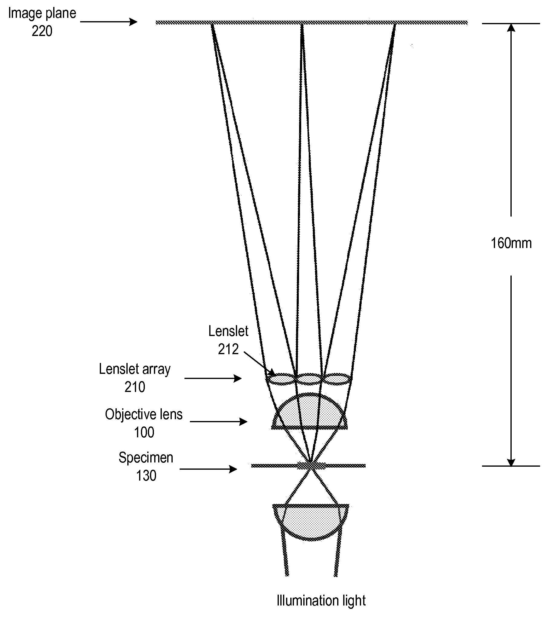
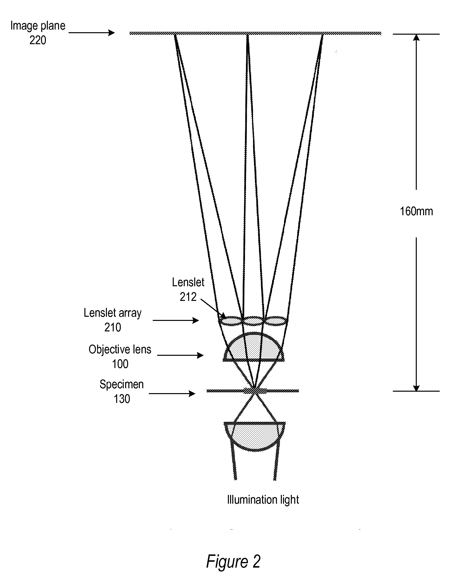
[0028]Various embodiments of a method and apparatus for a light field microscope that may be used for real time three-dimensional (3D) microscopy and that incorporates a lenslet array at or near the rear aperture of an objective lens are described. A microscope objective lens is of very strong power (and thus of small focal length), especially at high magnification. Quality microscope objective lenses are highly optimized, corrected for chromatic and other aberrations, planar and strongly specialized in different ways. The objective lens is the single most expensive component in a conventional microscope. Replacing the objective lens with an uncorrected array of lenslets may not be feasible. Thus, embodiments supplement the objective lens with an array of low power lenslets which may be located at or near the rear aperture of the objective lens, and which slightly modify the objective lens. The result is a new type of objective lens, or an addition to existing objective lenses. Embo...


PUM


Abstract

A light field microscope incorporating a lenslet array at or near the rear aperture of the objective lens. The microscope objective lens may be supplemented with an array of low power lenslets which may be located at or near the rear aperture of the objective lens, and which slightly modify the objective lens. The result is a new type of objective lens, or an addition to existing objective lenses. The lenslet array may include, for example, 9 to 100 lenslets (small, low-power lenses with long focal lengths) that generate a corresponding number of real images. Each lenslet creates a real image on the image plane, and each image corresponds to a different viewpoint or direction of the specimen. Angular information is recorded in relations or differences among the captured real images. To retrieve this angular information, one or more of various dense correspondence techniques may be used.

Description

BACKGROUND[0001]1. Field of the Invention[0002]This invention relates to microscopy, and more specifically to three-dimensional light field microscopy.[0003]2. Description of the Related Art[0004]FIG. 1 illustrates a prior art light field microscope that may be used for real time three-dimensional (3D) microscopy. The light field microscope is based on a conventional microscope, modified by inserting a microlens array 110 containing tens or hundreds of thousands of microlenses at the intermediate image plane 120, at or about 2.5 millimeters (mm) in front of the sensor (e.g., a charge coupled device (CCD)). This microlens array transposes the light field, producing an array of, for example, 55,000 small images of the rear aperture of the objective lens 100. The images capture the directional (angular) information of the light field, while each microlens location corresponds to spatial information. In this way, the 3D light field is multiplexed onto the 2D surface of the sensor.[0005]...

Claims


Application Information

Patent Timeline
Patent Type & Authority Applications(United States)
IPC IPC(8): G02B21/00
CPCG02B3/0006G02B21/367G02B21/361G02B21/02
Inventor GEORGIEV, TODOR G.
Owner ADOBE SYST INC
Why Eureka
Try Eureka