Read operation control sequencing apparatus, systems, and methods

a technology of read operation control and sequencing apparatus, applied in the field of apparatus, systems, and methods associated with information storage and processing, can solve the problems of increasing read time, increasing design and process challenges, and mlc read operations can take longer than read operations for single cells

Active Publication Date: 2008-07-31
MICRON TECH INC
View PDF5 Cites 16 Cited by
  • Summary
  • Abstract
  • Description
  • Claims
  • Application Information

AI Technical Summary

Problems solved by technology

However, the resulting feature size can give rise to design and process challenges.
However, this solution results in increasingly long read times, so that MLC read operations can take longer than read operations for single cells.

Method used


Image

  • Read operation control sequencing apparatus, systems, and methods
  • Read operation control sequencing apparatus, systems, and methods
  • Read operation control sequencing apparatus, systems, and methods

Examples


Embodiment Construction

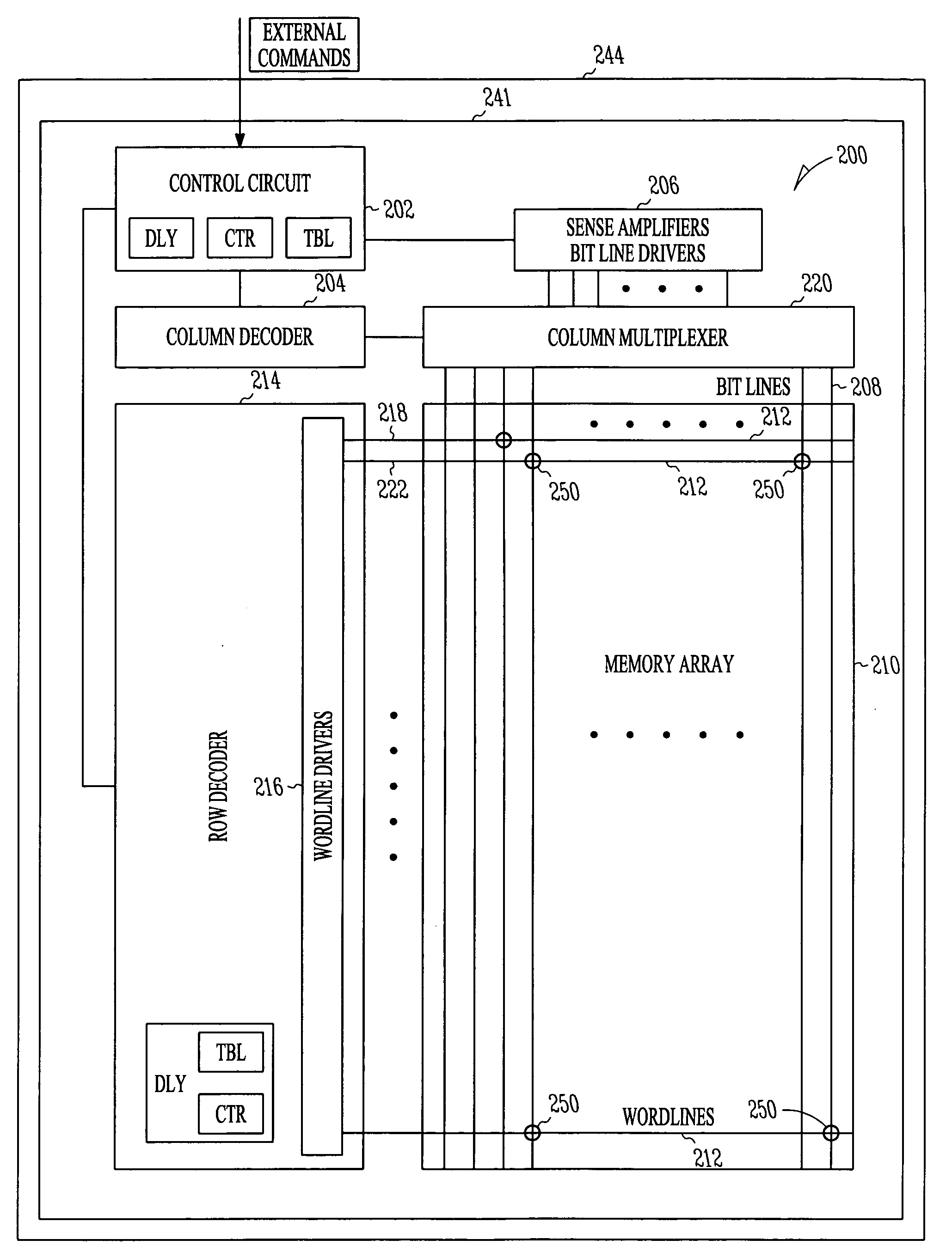
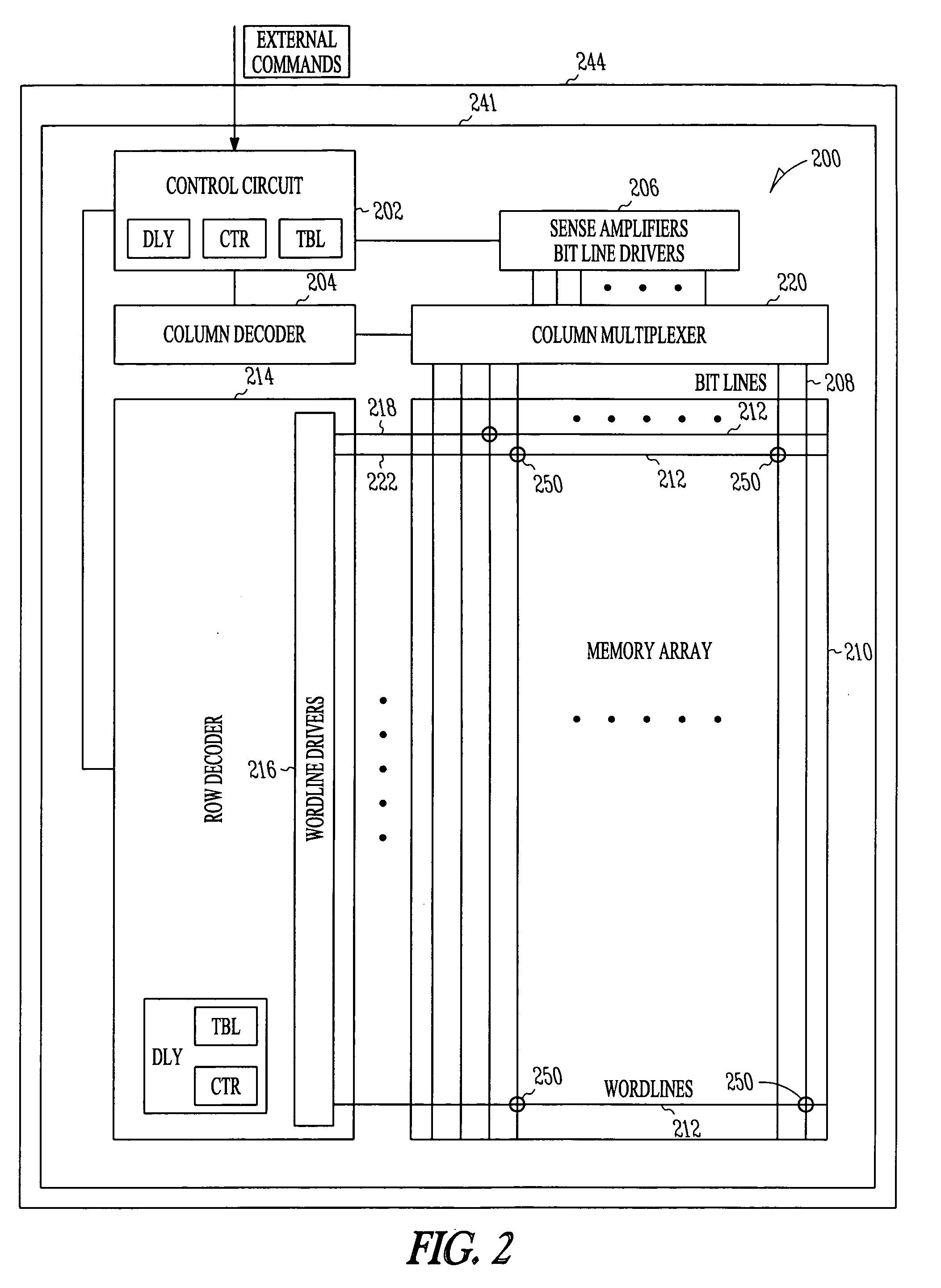
[0011]To address the challenges described above, various embodiments described herein may operate to provide a revised control sequence for memory cell read operations. Instead of driving all wordlines to their ultimate voltages at the same time, the wordline coupled to a selected cell may be held at ground potential while the unselected wordlines are driven to normal levels. After a suitable delay that corresponds to the read voltage level in use, the selected wordline may then be activated, or driven to its target level. This sequence allows all wordlines to settle toward their ultimate voltages more quickly.

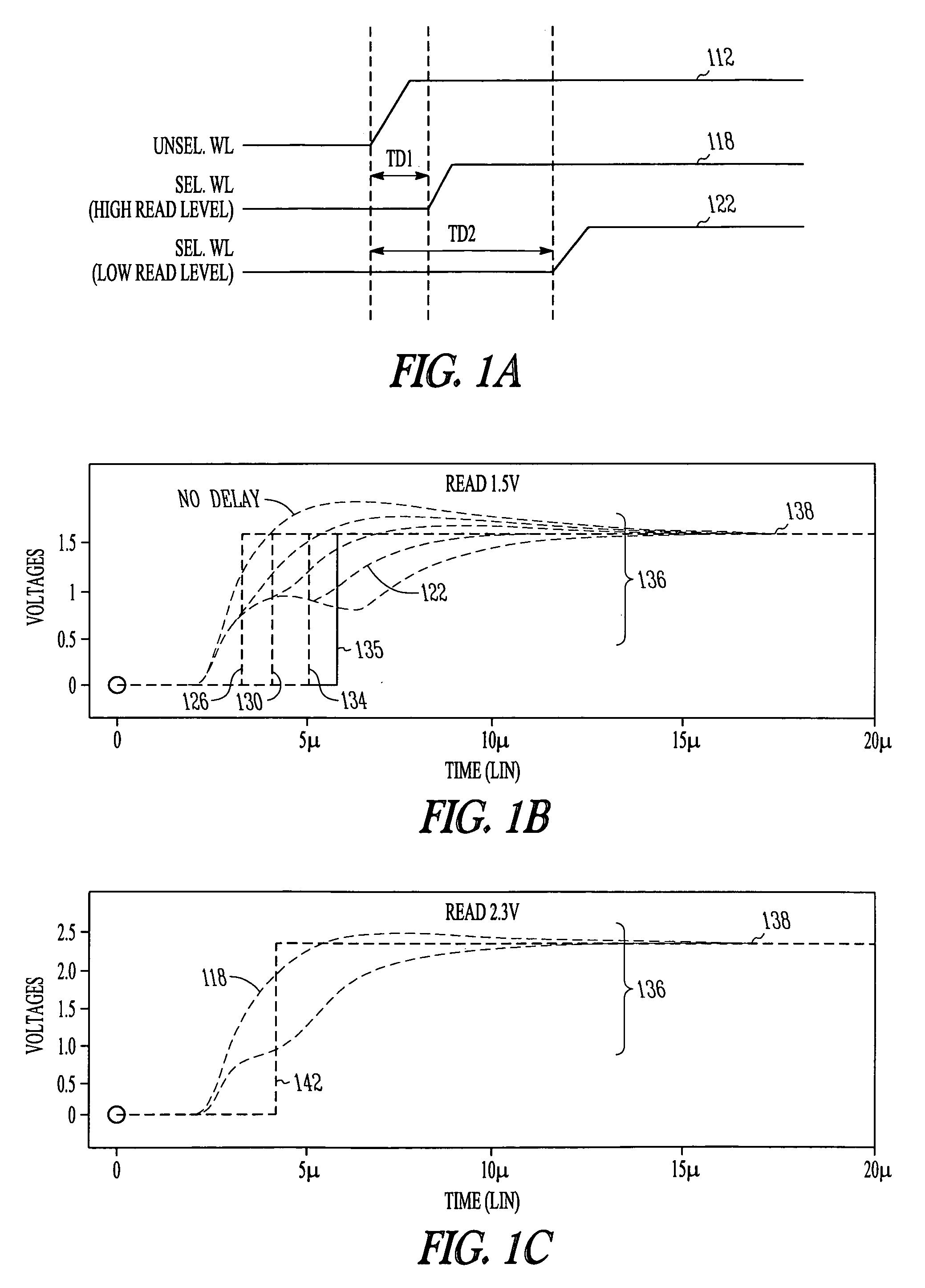
[0012]FIG. 1A is a signal diagram illustrating relative amplitudes of wordline 112, 118, 122 voltages during read operations conducted according to various embodiments of the invention. Here it can be seen that inventive embodiments include operating so as to delay the activation of some wordlines (e.g., selected high read level wordline 118 and / or selected low read level word...


PUM


Abstract

Apparatus, systems, and methods described herein may operate to receive an external read command at a control circuit coupled to a memory array. Individual wordline activation may be delayed according to a delay period determined by a read level voltage magnitude associated with a plurality of memory cells included in the array.

Description

TECHNICAL FIELD [0001]Various embodiments described herein relate to apparatus, systems, and methods associated with information storage and processing, including the operation and manufacture of memories having volatile and non-volatile storage.BACKGROUND INFORMATION [0002]Continuously reducing the size of solid-state memory architecture is an effective way to increase the capacity of such memories for a given amount of circuit real estate. However, the resulting feature size can give rise to design and process challenges. For example, the resistive-capacitive delay along wordlines in a memory array can dramatically increase with feature size reduction, providing strong electrical coupling between adjacent wordlines. The effects can most easily be seen as a reduction of the read threshold voltage (Vt) margin. As the wordlines in an array (both selected and unselected) are driven to desired values at about the same time, the far end of selected wordlines is often coupled to a voltag...

Claims


Application Information

Patent Timeline
Patent Type & Authority Applications(United States)
IPC IPC(8): G11C7/00
CPCG11C8/14G11C16/32G11C16/08G11C11/5642
Inventor YU, XIAOJUNHAN, JIN-MAN
Owner MICRON TECH INC
Why Eureka
Try Eureka