Process and apparatus for a wavelength tuning source

a wavelength tuning and filter technology, applied in the field of optical wavelength filter systems, can solve the problems of limiting the maximum tuning speed, the sweep frequency previously demonstrated is less than 1 khz limited by finite tuning speed of filters, etc., and achieves low spontaneous emission background and low tuning rate

Active Publication Date: 2008-07-31
THE GENERAL HOSPITAL CORP
View PDF99 Cites 21 Cited by
  • Summary
  • Abstract
  • Description
  • Claims
  • Application Information

AI Technical Summary

Benefits of technology

[0017]In one further exemplary embodiment of the present invention, a high-speed tuning of an extended-cavity semiconductor laser may be provided. The laser resonator may include a unidirectional fiber-optic ring, a semiconductor optical amplifier as the gain medium, and a scanning filter based on a polygon scanner. Variable tuning rates of up to 1,150 nm / ms (15.7 kHz repetition frequency) can be obtained over a 70 nm wavelength span centered at 1.32 μm. Such tuning rate can be more than an order of magnitude faster than is conventionally know, and may be facilitated in part by self-frequency shifting in the semiconductor optical amplifier. The instantaneous line width of the source may be <0.1 nm for 9-mW cw output power, and a low spontaneous-emission background of 80 dB can be obtained.

Problems solved by technology

Obtaining single-frequency laser operation and ensuring mode-hop-free tuning, however, may use a complicated mechanical apparatus and limit the maximum tuning speed.
However, the sweep frequency previously demonstrated has been less than 1 kHz limited by finite tuning speeds of the filters.

Method used


Image

  • Process and apparatus for a wavelength tuning source
  • Process and apparatus for a wavelength tuning source
  • Process and apparatus for a wavelength tuning source

Examples


Embodiment Construction

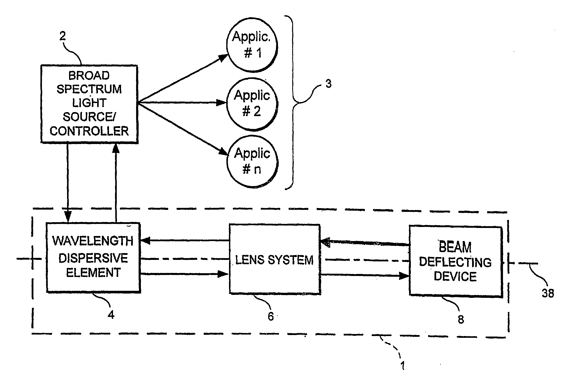
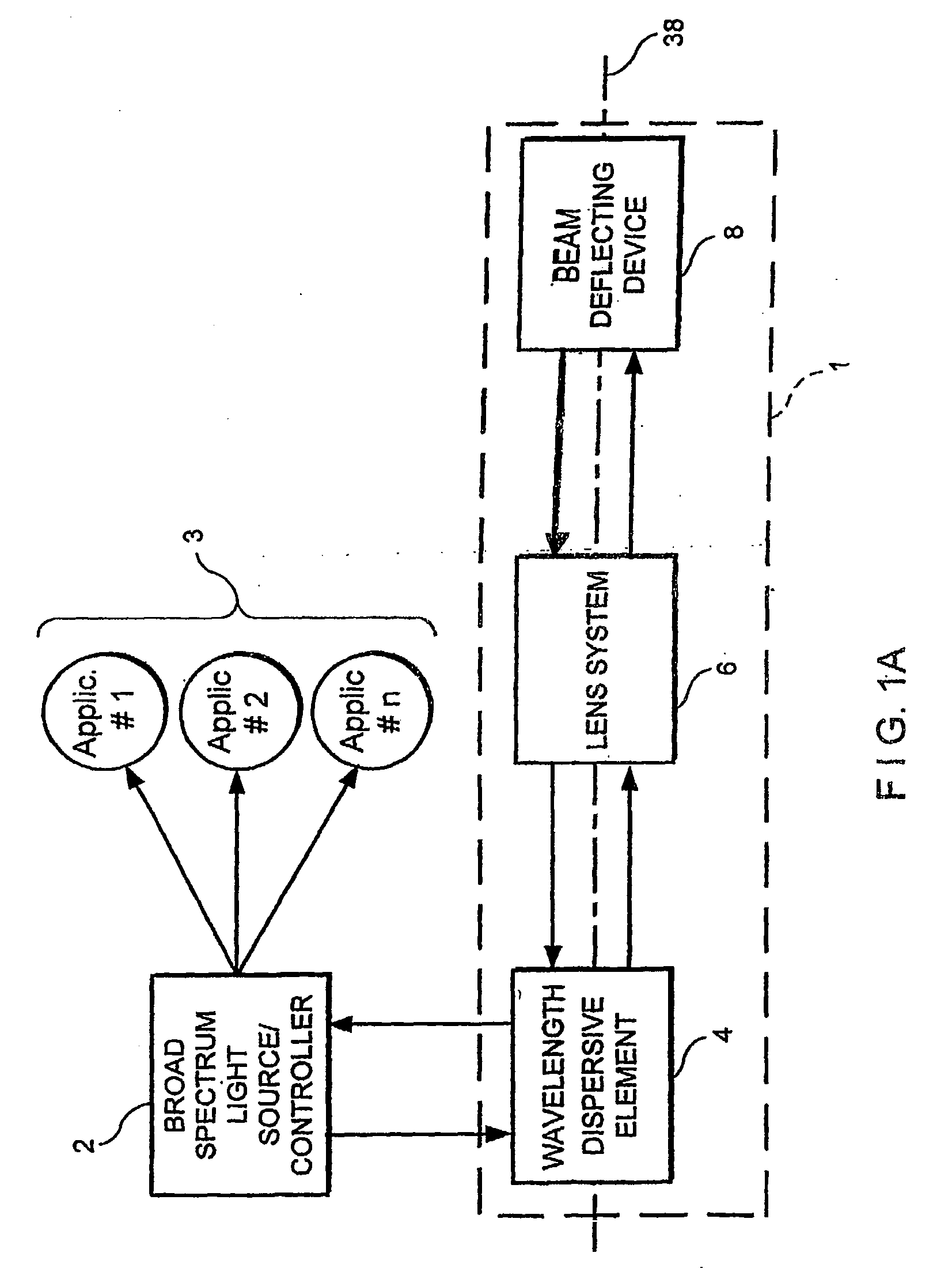
[0037]FIG. 1A shows a block diagram of a first exemplary embodiment of an optical wavelength filter 1 in accordance the present invention. In this first exemplary embodiment, the optical wavelength filter 1 can be used in a variety of different applications, general examples of which are described below. In this example, the filter 1 may be coupled to one or more applications 3 via a light source 2. It should be understood that in certain exemplary applications, the filter 1 can be used with or connected to an application (e.g., one or more of the applications 3) via a device other than a light source (e.g. a passive or active optical element). In the first exemplary embodiment shown in FIG. 1A, a broad spectrum light source and / or controller 2 (hereinafter referred to as “light controller”), may be coupled to a wavelength dispersing element 4. The light controller 2 can be further coupled to one or more of the applications 3 that are adapted to perform one or more tasks with or for...


PUM

PropertyMeasurementUnit
mean frequencyaaaaaaaaaa
line widthaaaaaaaaaa
lengthaaaaaaaaaa

Abstract

An apparatus and source arrangement for filtering an electromagnetic radiation can be provided which may include at least one spectral separating arrangement configured to physically separate one or more components of the electromagnetic radiation based on a frequency of the electromagnetic radiation. The apparatus and source arrangement may also have at least one continuously rotating optical arrangement which is configured to receive at least one signal that is associated with the one or more components. Further, the apparatus and source arrangement can include at least one beam selecting arrangement configured to receive the signal.

Description

CROSS-REFERENCE TO RELATED APPLICATIONS[0001]The present application is a divisional of U.S. patent application Ser. No. 10 / 861,179 filed Jun. 4, 2004. This application also claims priority from U.S. Patent Application Ser. No. 60 / 476,600 filed on Jun. 6, 2003, and U.S. Patent Application Ser. No. 60 / 514,769 filed on Oct. 27, 2003, the entire disclosure of which is incorporated herein by reference.FIELD OF THE INVENTION[0002]The present invention relates generally to optical systems and more particularly to an optical wavelength filter system for wavelength tuning.BACKGROUND OF THE INVENTION[0003]Considerable effort has been devoted for developing rapidly and widely tunable wavelength laser sources for optical reflectometry, biomedical imaging, sensor interrogation, and tests and measurements. A narrow line width, wide-range and rapid tuning have been obtained by the use of an intra-cavity narrow band wavelength scanning filter. Mode-hopping-free, single-frequency operation has been...

Claims


Application Information

Patent Timeline
Patent Type & Authority Applications(United States)
IPC IPC(8): H01S3/10G02B5/32A61B5/00G01J3/12G01J9/02G01N21/47G02B27/48
CPCA61B5/0059G01B9/02091G01J3/10G01J3/12G01J9/0215G01N21/4795G02B27/48H01S3/08009H01S3/08063H01S3/105H01S5/141H01S5/146H01S5/4087G01B9/02004A61B5/0066A61B5/00G01J9/02G02B5/20G02B27/46
Inventor BOUMA, BRETT EUGENEYUN, SEOK-HYUN ANDYOH, WANG-YUHL WILLIAMDE BOERTEARNEY, GUILLERMO J.
Owner THE GENERAL HOSPITAL CORP
Why Eureka
Try Eureka