Crash impact attenuator systems and methods

a technology of attenuator and impact, which is applied in the direction of roadway safety arrangements, roads, construction, etc., can solve the problem of much more difficult recovery to its original cylindrical shap

Active Publication Date: 2008-07-31
TRAFFIX DEVICES INC
View PDF27 Cites 22 Cited by
  • Summary
  • Abstract
  • Description
  • Claims
  • Application Information

AI Technical Summary

Benefits of technology

[0009]An important feature of the present invention is its ability to recover to its original state after vehicular impact. When the attenuator elements of the invention are fully deflected or flattened, the deformation is limited to that corresponding to bending from its initial curvature to a substantially straight configuration, and is nearly constant. By contrast, a cylinder, when flattened, has extreme deformation at the outer edges so that recovery to its original cylindrical shape is much more difficult. Each inventive attenuator element can be fully flattened and recovered before installation of the crash attenuator unit. This pre-loading improves the shape recovery after impact.
[0021]Importantly, each of the plurality of energy absorbing modules are pre-compressed, so that, after impact, they are capable of rebounding to substantially their pre-impact configuration. This permits the inventive crash attenuator to be completely reusable.

Problems solved by technology

By contrast, a cylinder, when flattened, has extreme deformation at the outer edges so that recovery to its original cylindrical shape is much more difficult.

Method used


Image

  • Crash impact attenuator systems and methods
  • Crash impact attenuator systems and methods
  • Crash impact attenuator systems and methods

Examples


Embodiment Construction

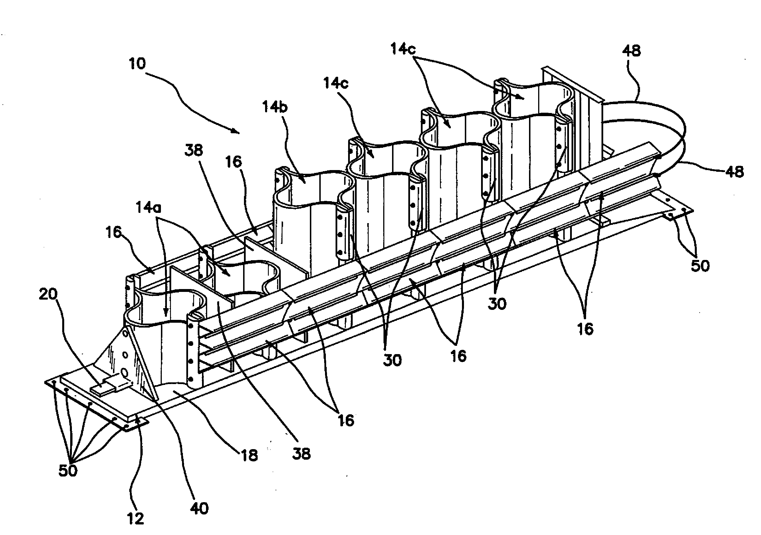
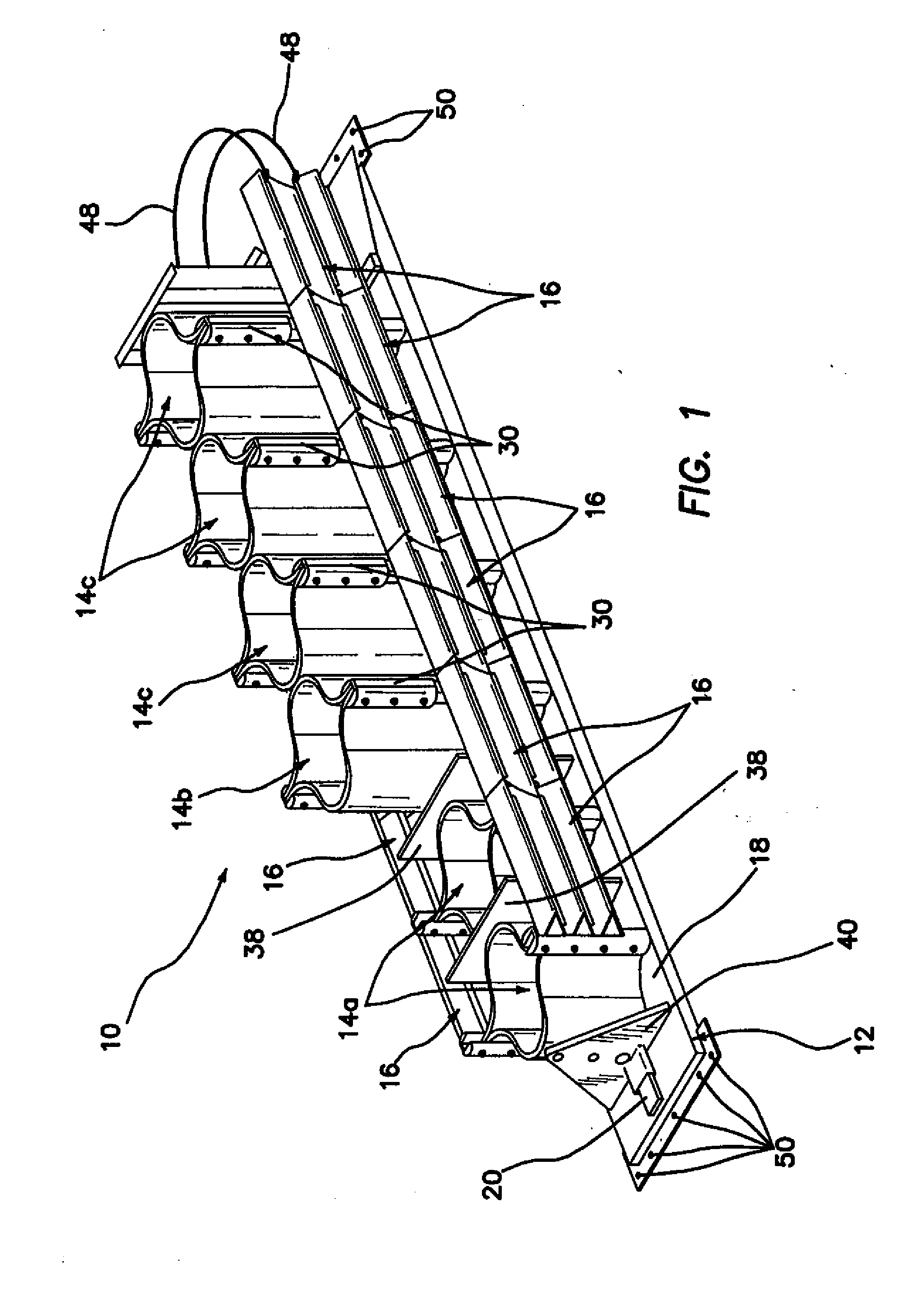
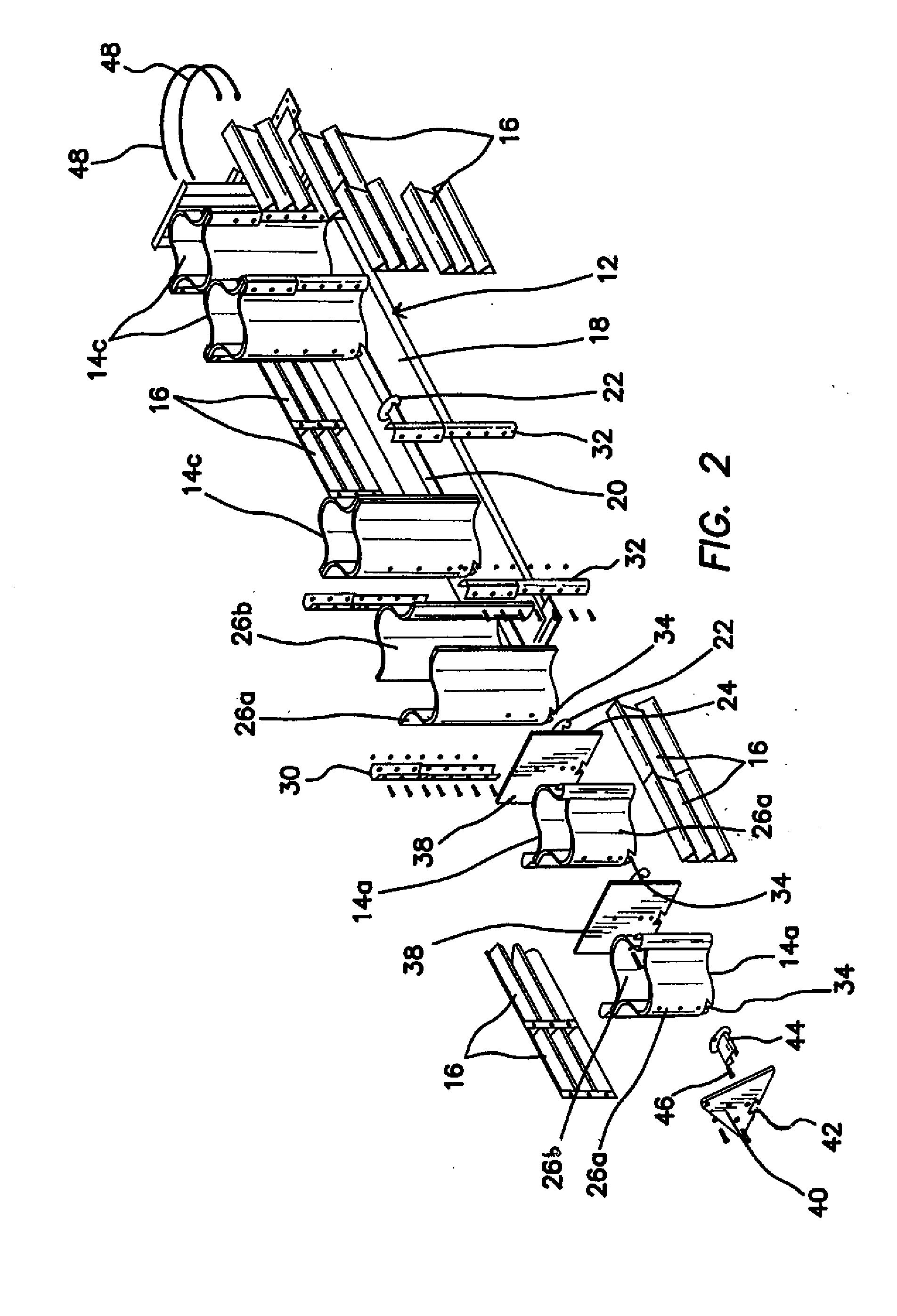
[0036]Referring now more particularly to the drawings, there is shown in FIGS. 1-5 a crash attenuator 10 which incorporates the features of the present invention. The major components of the attenuator 10 include a mounting base 12, preferably fabricated of steel or other suitable metal or material, a plurality of energy absorbing modules 14a, 14b, and 14c, and a plurality of fender panels 16. The inventive attenuator 10 is referred to in the traffic safety industry as a re-directive, non-gating crash cushion. It is designed to be employed between concrete bridge abutments and the like, usually for the purpose of protecting the occupants of an errant vehicle from the effects of a collision with such an immovable object. Occasionally, the inventive crash cushion may be utilized to protect an object which cannot withstand the force of an un-cushioned impact from a vehicle.

[0037]In a preferred embodiment, the crash attenuator 10 has a total length of approximately 255.25 inches (6.5 m)...


PUM


Abstract

A reusable energy-absorbing crash attenuator comprises a base, a rail disposed on and extending along a length of the base, and a plurality of energy absorbing modules slidably disposed on the rail. Each of the energy absorbing modules comprises a first module portion and a second module portion which are attached together. Each of the module portions comprise plastic, preferably high density polyethylene (HDPE), and have a combination of concave and convex curvature. A plurality of fender panels are disposed in adjoining end-to-end fashion along each side of the length of the crash attenuator. The fender panels are arranged to slide together in telescoping fashion upon impact of the crash attenuator by a vehicle.

Description

[0001]This application claims the benefit under 35 U.S.C. 119(e) of the filing date of Provisional U.S. Application Ser. No. 60 / 898,243, entitled Crash Impact Attenuator Systems and Methods and filed on Jan. 29, 2007, which application is commonly assigned herewith and herein expressly incorporated herein by reference, in its entirety.BACKGROUND OF THE INVENTION[0002]The present invention relates generally to crash impact attenuators, and more particularly to motor vehicle and highway barrier crash impact attenuators constructed from molded plastic materials.[0003]Vehicular accidents on the highway are a major worldwide problem and are undoubtedly one of the largest causes of economic and human loss and suffering inflicted on the developed world today. In an effort to alleviate, in particular, the human toll of these tragic accidents, guardrails, crash cushions, truck-mounted crash attenuators, crash barrels, and the like have been developed to attenuate the impact of the vehicle wi...

Claims


Application Information

Patent Timeline
Patent Type & Authority Applications(United States)
IPC IPC(8): E01F15/00
CPCE01F15/146E01F15/0453
Inventor MCKENNEY, JOHN D.KULP, JACK H.
Owner TRAFFIX DEVICES INC
Why Eureka
Try Eureka