
Synthesis of Carbon Nanotubes by Selectively Heating Catalyst

a catalyst and selective heating technology, applied in the direction of chemically reactive gases, crystal growth process, polycrystalline material growth, etc., can solve the problems of high negative bias formation of wafers and device integration problems

Active Publication Date: 2008-07-31
CFD RES CORP
View PDF5 Cites 13 Cited by
  • Summary
  • Abstract
  • Description
  • Claims
  • Application Information

AI Technical Summary

Benefits of technology

The patent describes a device used to make certain chemical compounds at very low temperatures. This invention allows researchers to create new materials with specific properties that can be useful in various applications.

Problems solved by technology

The technical problem addressed in this patent is how to grow carbon nanotubes on sensitive substrates while avoiding damage caused by high temperatures. Existing methods involving plasma or RF sources result in high positive bias voltage on the substrate, causing difficulty in integrating devices. Additionally, there is no efficient way to selectively heat only the catalyst particles involved in producing carbon nanotubes.

Method used


Image

  • Synthesis of Carbon Nanotubes by Selectively Heating Catalyst
  • Synthesis of Carbon Nanotubes by Selectively Heating Catalyst
  • Synthesis of Carbon Nanotubes by Selectively Heating Catalyst

Examples


example 1

Synthesis of CNTs / CNFs Using Catalyst Selectively Heated by an Exothermic Reaction

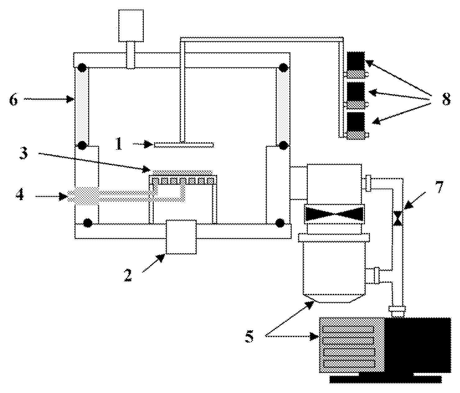
[0032]Experiments were conducted in a direct current (DC) PECVD system. Nickel catalyst films 100 Å thick were deposited on Si(100) substrate by electron beam evaporation or RF magnetron sputtering at a base pressure of 10−6 Torr. After catalyst deposition, the Si substrates were diced into chips and placed onto substrate in a PECVD system. After heating the samples to the desired growth temperature, the films were pretreated in NH3 DC plasma for 2 minutes to facilitate nanoparticle formation from the solid thin film. After pretreatment, acetylene and oxygen gases, were introduced and the growth of carbon nanofibers was performed for 10 min.

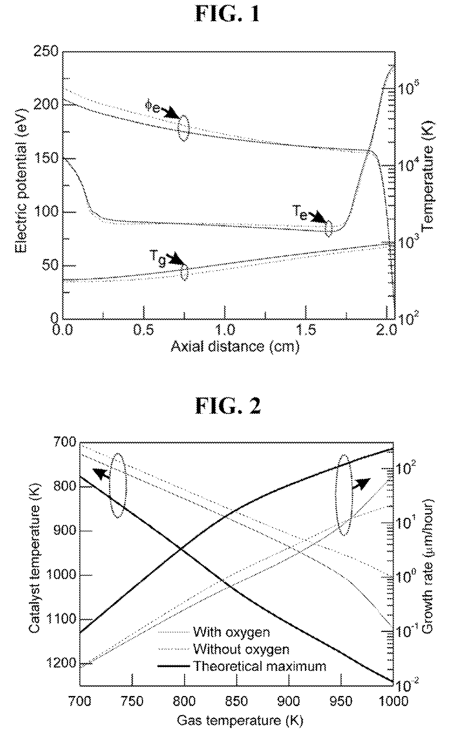
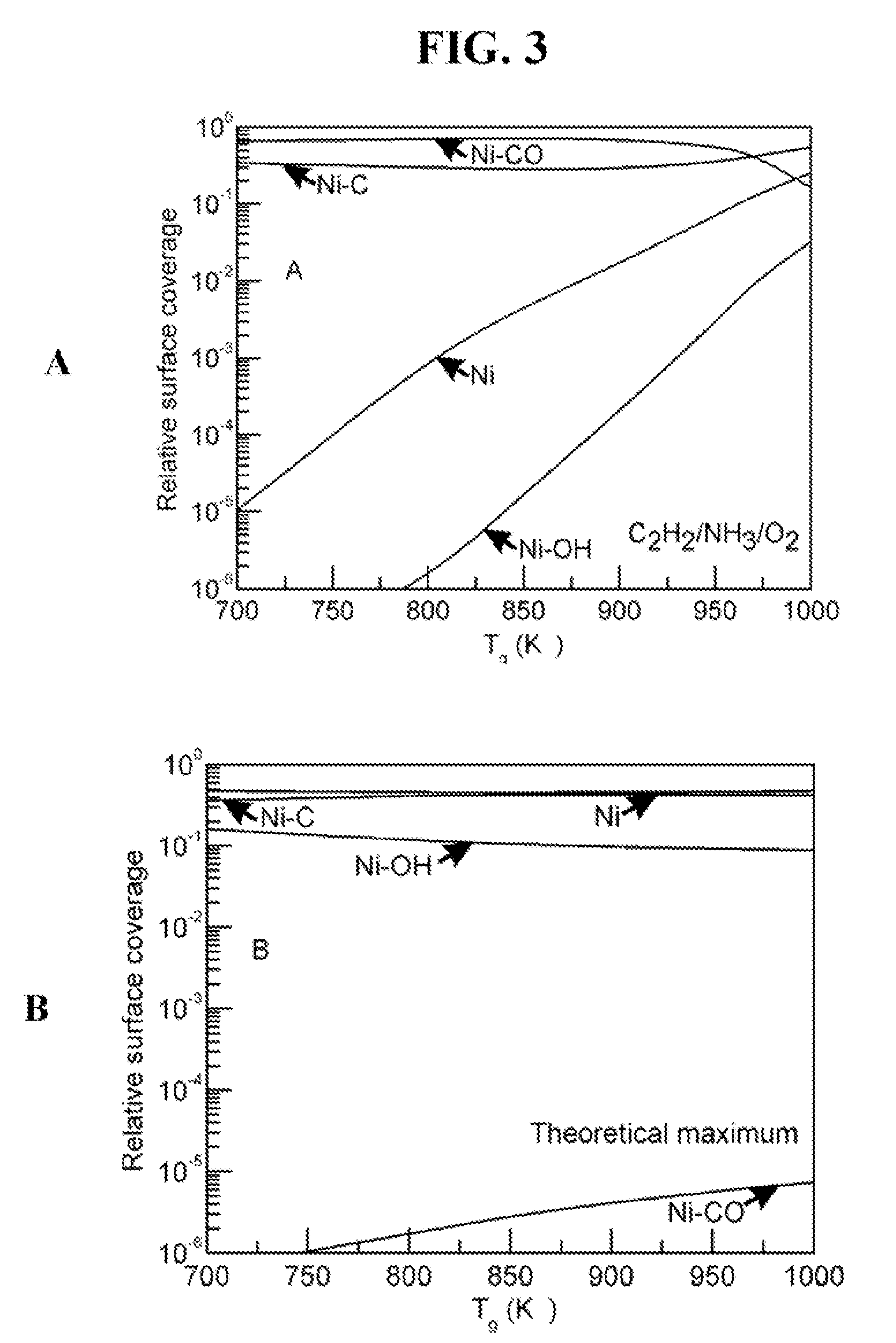
[0033]In order to obtain optimal growth conditions at lower temperature, experiments were performed starting at known optimized high temperature conditions for acetylene / ammonia gas mixtures, then gradually varied toward the lower temperature, plasma power, and incr...


PUM

PropertyMeasurementUnit
Frequencyaaaaaaaaaa
Frequencyaaaaaaaaaa
Frequencyaaaaaaaaaa

Abstract

The present invention is a catalytic chemical vapor deposition method and apparatus for synthesizing carbon nanotubes and/or carbon nanofibers (CNTs) on a substrate by selectively heating a catalyst for CNT synthesis on or near the surface of the substrate. Selective heating of the catalyst is achieved using an exothermic oxidation reaction on the surface of the catalyst, inductive heating from a radio frequency source, or both. Selective heating of the catalyst prevents heating of the substrate and enables the synthesis of CNTs on temperature sensitive substrates.

Description


Claims


Application Information

Patent Timeline
Owner CFD RES CORP
Learn More