Apparatus for moving a misplaced or impacted tooth

a technology a misplaced tooth, which is applied in the field of apparatus for moving an impacted tooth, can solve the problems of not making the necessary tension adjustment, patients are often unreliable in following orthodontist's instructions,

Inactive Publication Date: 2008-07-31
SPALTY CORY J
View PDF4 Cites 38 Cited by
  • Summary
  • Abstract
  • Description
  • Claims
  • Application Information

AI Technical Summary

Problems solved by technology

Patients are often unreliable in following their orthodontist's instructions; and,...

Method used


Image

  • Apparatus for moving a misplaced or impacted tooth
  • Apparatus for moving a misplaced or impacted tooth
  • Apparatus for moving a misplaced or impacted tooth

Examples


Embodiment Construction

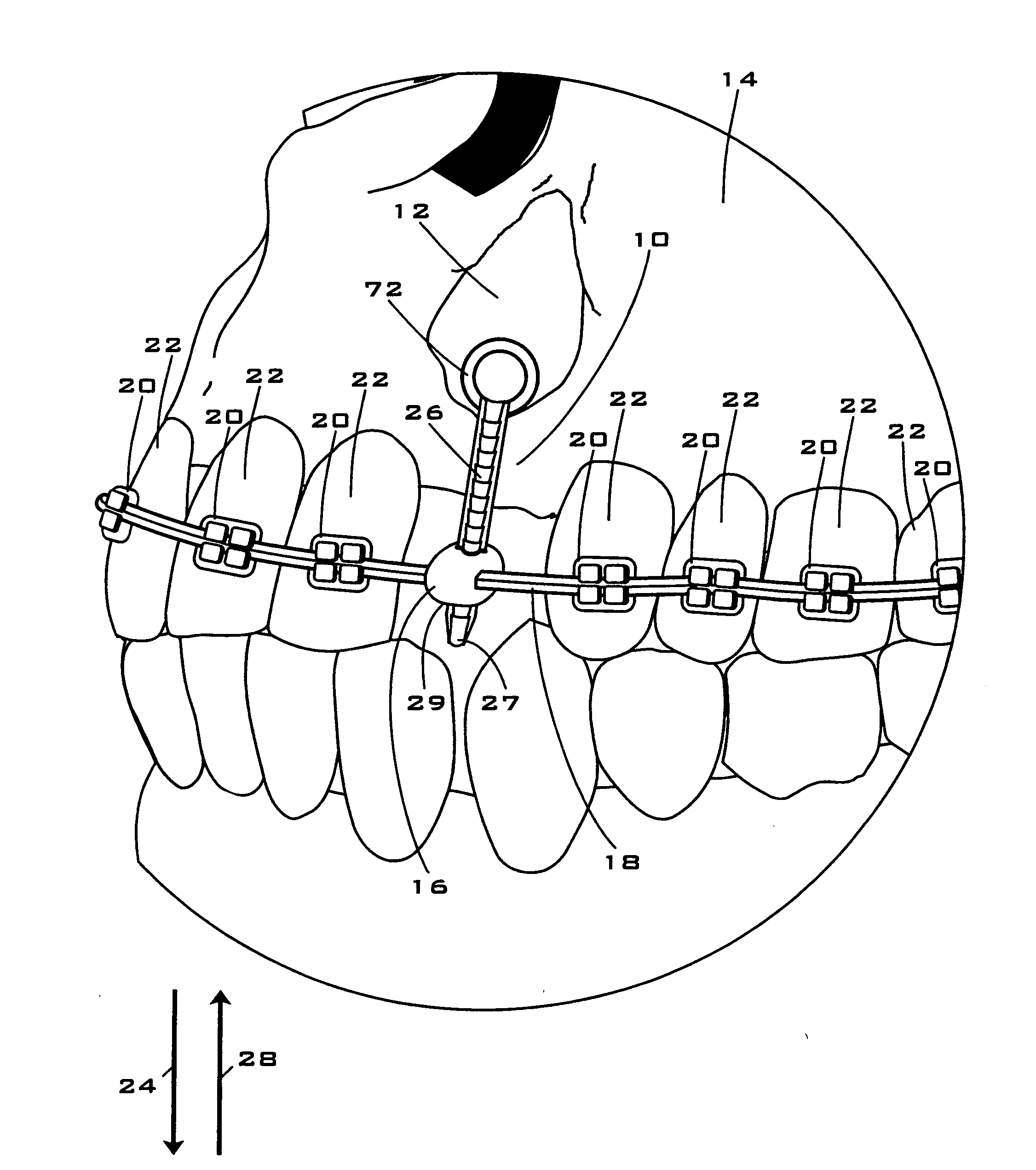
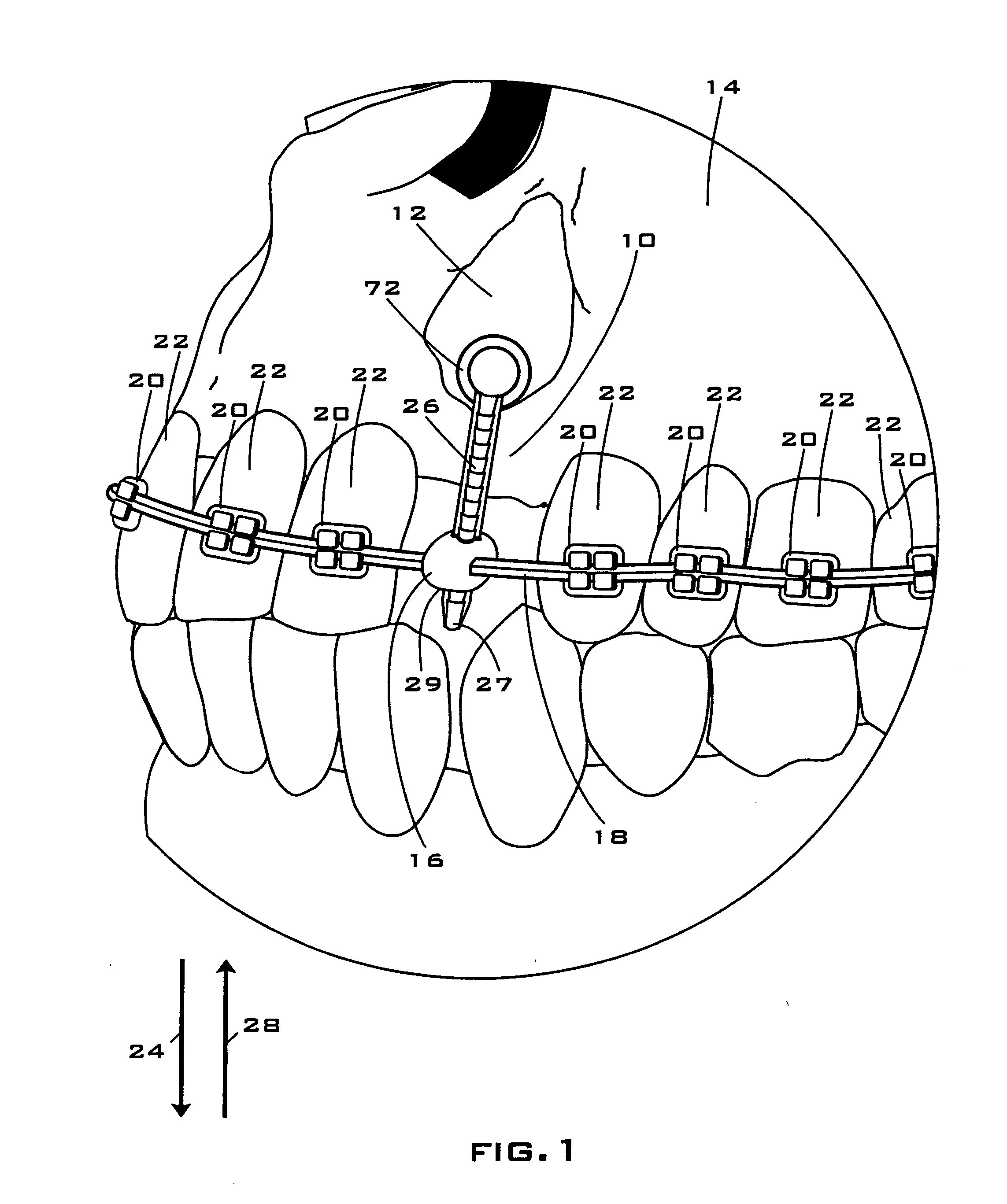
[0020]FIG. 1 is partial schematic view of an orthodontic assembly 10 that is connected to a misplaced or impacted tooth 12 within a patient's mouth 14. In the preferred embodiment depicted, the orthodontic assembly 10 is comprised of a locking mechanism 16 connected to an arch wire 18. The archwire 18, in turn, is connected via brackets 20 to teeth 22.

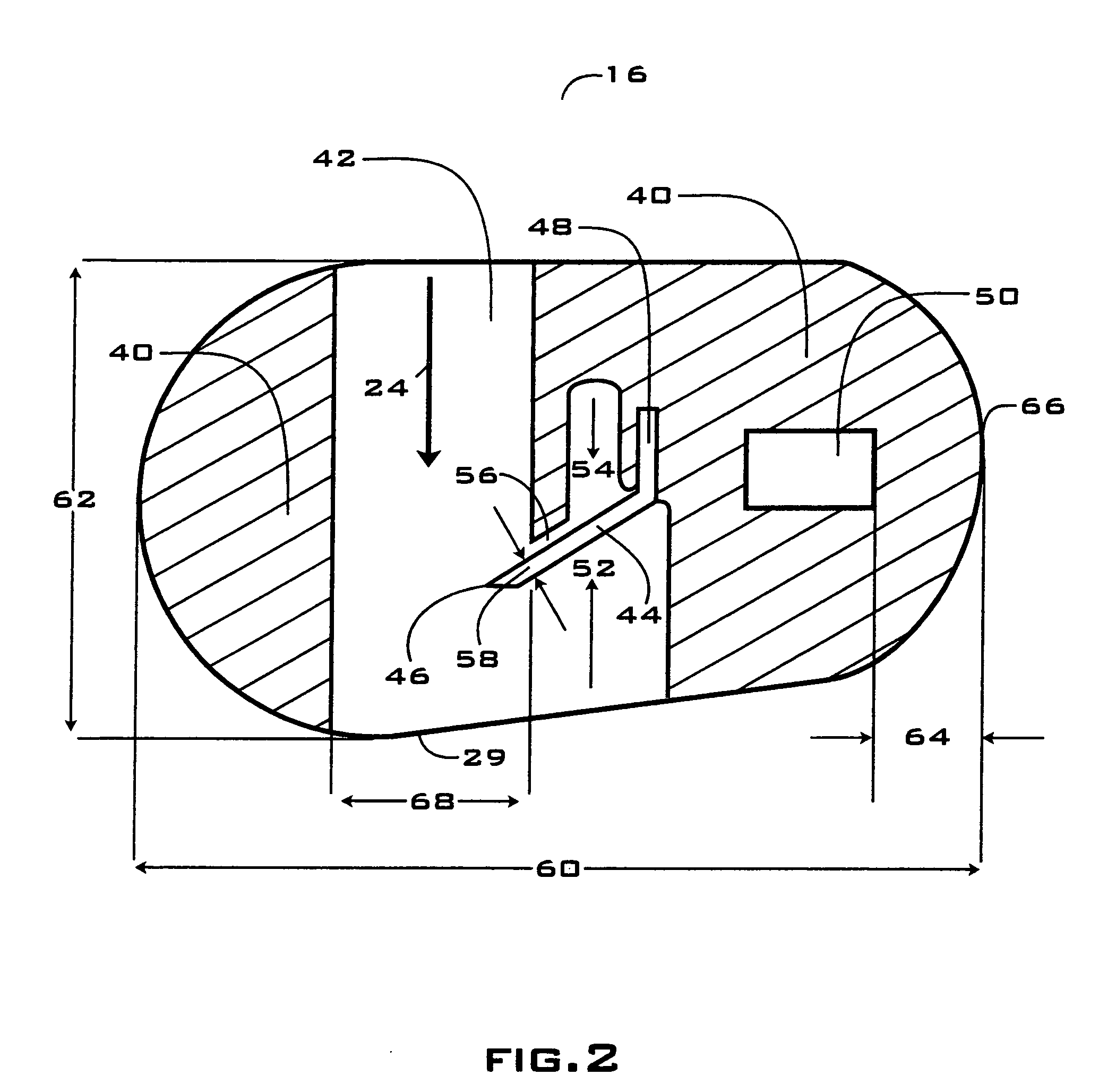
[0021]The locking mechanism 16 preferably provides unilateral locking, allowing movement in one direction but preventing movement in the opposite direction. In one embodiment, the locking mechanism 16 prevents rotation of the ligature within such locking mechanism due to the interaction of one or more rails on the ligature disposed within one or more slots in the locking mechanism.

[0022]Referring again to FIG. 1, when pressure is applied to locking mechanism 16 in the direction of arrow 28, ligature 26 is displaced within such locking mechanism in the direction of arrow 24 so that arch wire 18 is pulled upwardly in the direction of arr...


PUM


Abstract

A self-adjusting apparatus for moving an impacted tooth, wherein said apparatus is comprised a locking mechanism, an archwire disposed within said locking mechanism, and a ligature movably connected to said locking mechanism.

Description

CROSS-REFERENCE TO RELATED PATENT APPLICATION[0001]This application claims priority based upon applicant's provisional patent applications Nos. 60 / 898,308 (filed on Jan. 30, 2007), 60 / 903,383 (filed on Feb. 26, 2007), and 60 / 926,949 (filed on Apr. 30, 2007),FIELD OF THE INVENTION[0002]An apparatus for bringing a misplaced or impacted tooth into proper alignment within a patient's mouth.BACKGROUND OF THE INVENTION[0003]The prior art has addressed the problem of moving a tooth, such as an impacted canine, into an arch of teeth in a patient's mouth. As is disclosed in column 1 of U.S. Pat. No. 5,292,249 of Daniel S. German, “ . . . in the past, a force was applied to the misaligned tooth by a rubber elastic or a wire having one end affixed to the tooth and another end coupled to an arch wire which was typically mounted around the arch of teeth. The movement of the tooth was accomplished in large part by rapid movement of the tooth which occurred immediately following visits with an ort...

Claims


Application Information

Patent Timeline
IPC IPC(8): A61C7/22
CPCA61C7/00A61C7/22A61C7/12
Inventor SPALTY, CORY J.
Owner SPALTY CORY J
Why Eureka
Try Eureka