New type electric impact drill

A technology of electric impact drill and impact block, which is used in portable impact tools, striking tools, portable drilling rigs, etc., can solve the problems of no oil leakage prevention structure, annealing of impact teeth, damaged impact drill, etc., to ensure the anti-interference effect and improve the Service life, guarantee the effect of normal operation

Inactive Publication Date: 2009-11-25
吴世雄
View PDF8 Cites 1 Cited by
  • Summary
  • Abstract
  • Description
  • Claims
  • Application Information

AI Technical Summary

Problems solved by technology

When the impact electric drill is working, the first impact tooth and the second impact tooth play a clutching role, which can generate axial impact force for the output shaft. However, due to the high impact frequency, not only local high temperature will be generated in this working position, The lubricating oil is also easily splashed to the non-working position, which not only causes a waste of lubricating oil, but more seriously causes the impact teeth to not be well lubricated, so it is easy to cause the impact teeth to be annealed and wear and reduce or not produce shaft Thrust and other adverse phenomena, so that the safety performance of the impact drill is greatly reduced, and even damage the entire impact drill
For example, a Chinese utility model patent ZL03205221.9 discloses an electric impact drill. When the impact gear (equivalent to the above-mentioned second impact tooth) in the patent meshes with the helical teeth of the fixed gear (equivalent to the above-mentioned first impact tooth), The transmission device drives the output shaft to rotate and at the same time moves the output shaft longitudinally, but since the outer circumference of the impact gear and the fixed gear is not provided with an oil leakage prevention structure, the impact electric drill of this patent also has the above-mentioned defects when working

Method used


Image

  • New type electric impact drill
  • New type electric impact drill
  • New type electric impact drill

Examples


Embodiment Construction

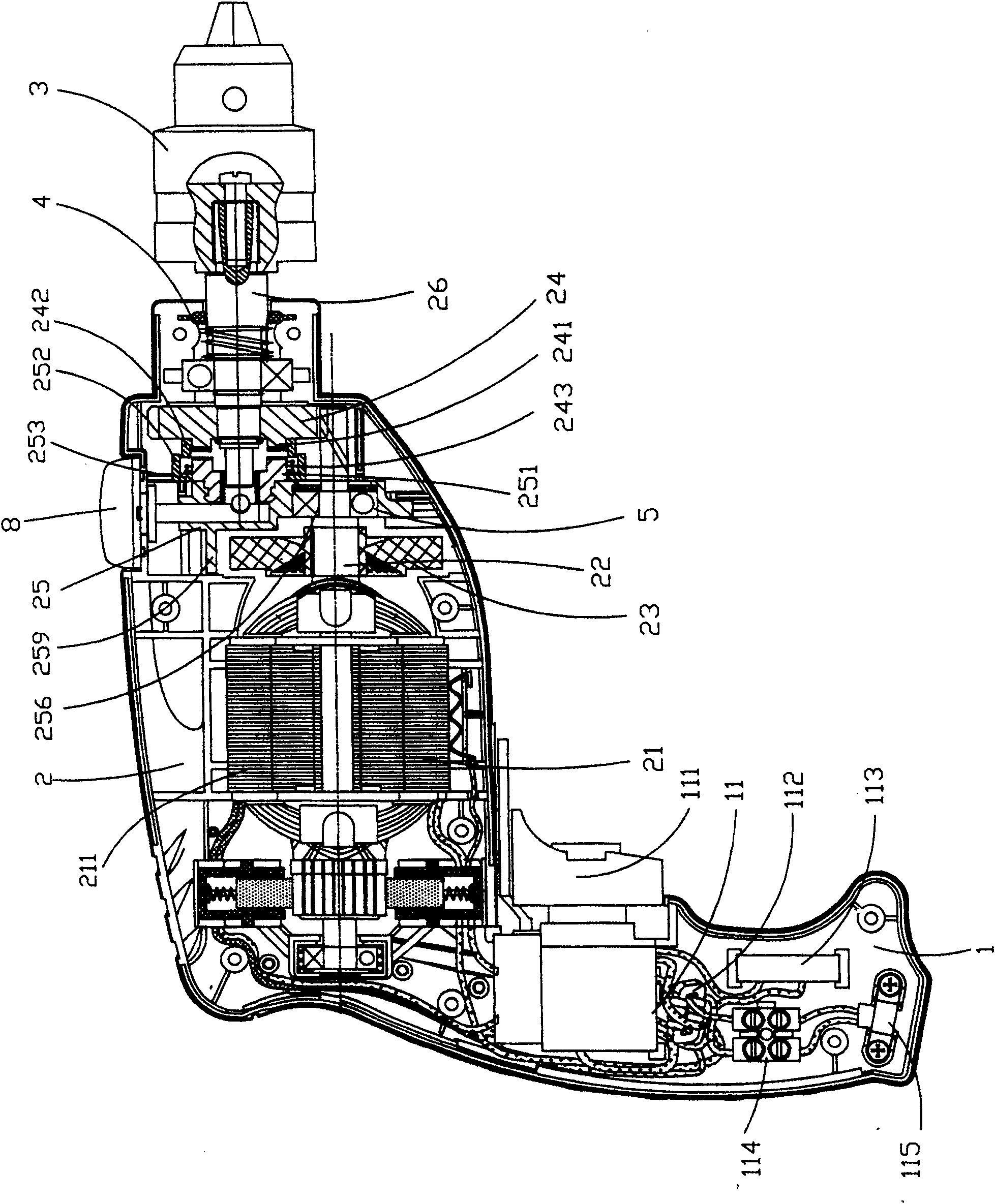
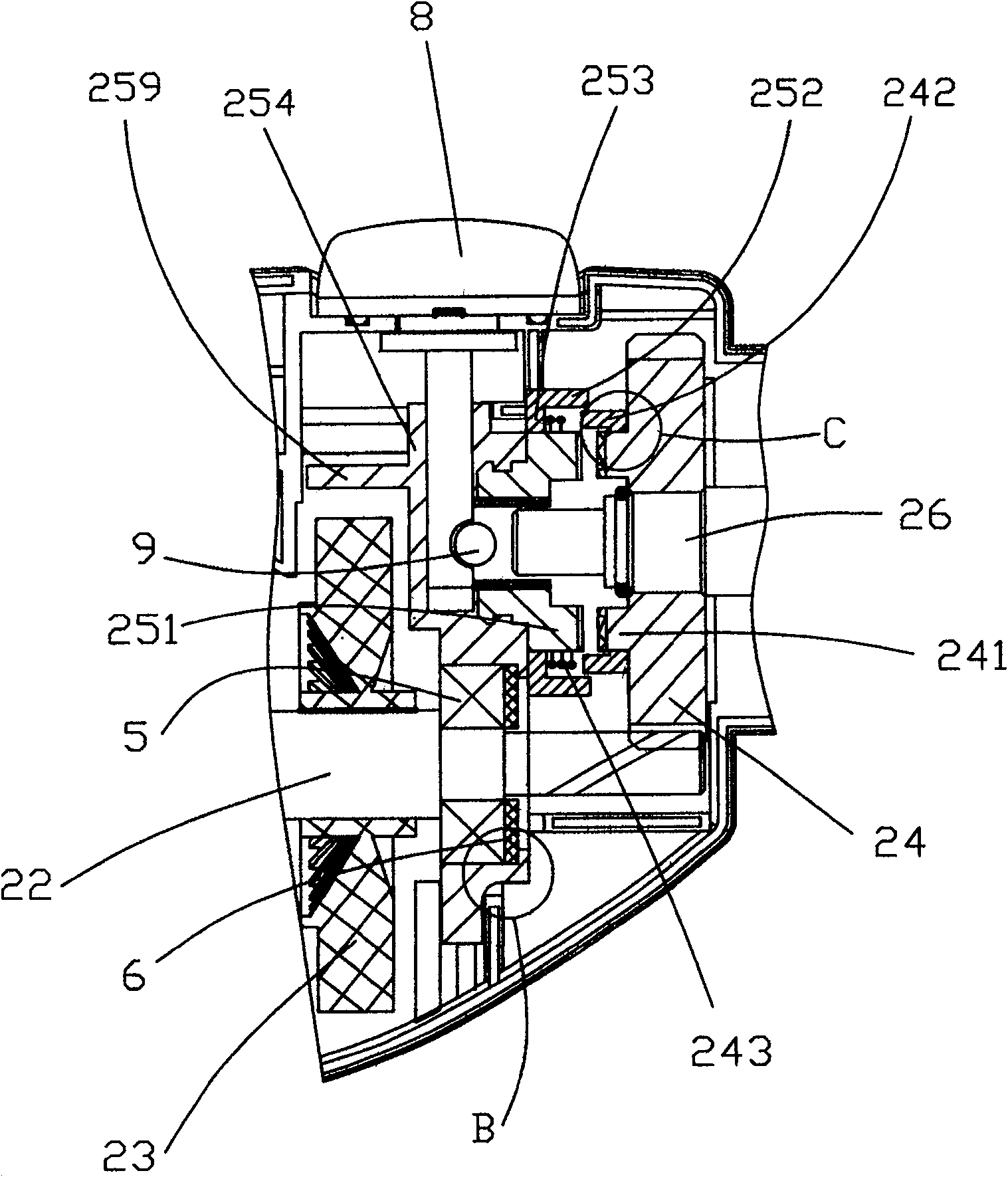
[0029] refer to figure 1 , figure 2 , image 3 and Figure 4 According to the electric impact drill provided by the present invention, it includes a handle 1, a body 2 and a drill chuck 3, a switch assembly 11 is installed at the handle portion; a motor 21 controlled by the switch assembly 11 is installed in the body 2, and a motor driven by the motor 21 Shaft 22, cooling device 23 installed on the output end of motor shaft 22, transmission gear 24 meshed with the end of motor shaft 22, impact device 25 between cooling device 23 and transmission gear 24, output shaft 26 fixed on transmission gear 24 ; The drill chuck 3 is installed on the end of the output shaft 26 protruding from the body 2 . The inner surface of the transmission gear 24 is provided with a first impact tooth 241, and the corresponding part of the impact device 25 is provided with a second impact tooth 251 that cooperates with it; the outer circumference of the first impact tooth 241 is provided with a fir...


PUM


Abstract

The invention relates to a novel impact electric drill that includes handle, frame and drill chuck. Switch component is installed on handle. Motor, motor shaft, heat sink, driving gear, impact device and output shaft are installed in the frame. The drill chuck is installed on one end extending out of the frame. A first impact tooth is set on the inner side surface of driving gear. The corresponding section of impact device has the second impact tooth. A first circle wall is set outside the first impact tooth. And the outside of the second impact tooth has the second circle wall matching with the first circle wall. The first circle wall and the second circle wall form sealed structure to make the impact teeth gain good lubrication all the time.

Description

technical field [0001] The invention relates to an electric tool, in particular to an impact electric drill. Background technique [0002] In the prior art, the technology of electric impact drills has matured day by day. It generally includes a handle, a body and a drill chuck. A motor, a motor shaft, a transmission gear, an output shaft, etc. are installed in the body. An impact tooth, the corresponding part of the impact device is provided with a second impact tooth matched with the first impact tooth. When the impact electric drill is working, the first impact tooth and the second impact tooth play a clutching role, which can generate axial impact force for the output shaft. However, due to the high impact frequency, not only local high temperature will be generated in this working position, The lubricating oil is also easily splashed to the non-working position, which not only causes a waste of lubricating oil, but more seriously causes the impact teeth to not be well ...

Claims


Application Information

Patent Timeline
Patent Type & Authority Patents(China)
IPC IPC(8): B23B45/16B23B45/02B23B47/00B25D16/00B25D17/00
Inventor 徐振丰
Owner 吴世雄
Why Eureka
Try Eureka