Impacted tooth traction apparatus

A traction device and technology of ambush teeth, applied in dentistry, orthodontics, dental prosthetics, etc., can solve the problems of difficulty in controlling the action point and direction of traction force, high bonding failure rate, and increasing attachment failures, etc. To achieve the effect of convenient surgical suture, small wound, and improve the success rate of bonding

Pending Publication Date: 2020-02-21
NANJING STOMATOLOGICAL HOSPITAL
View PDF0 Cites 1 Cited by
  • Summary
  • Abstract
  • Description
  • Claims
  • Application Information

AI Technical Summary

Problems solved by technology

Because the shape of the accessory base is not customized, the accessory usually does not fit the surgically exposed crown surface, which may greatly increase the risk of attachment failure; if the impacted tooth is located very deep in the alveolar bone, It is difficult for the light

Method used


Image

  • Impacted tooth traction apparatus
  • Impacted tooth traction apparatus
  • Impacted tooth traction apparatus

Examples


Embodiment 1

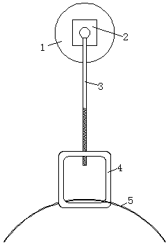
[0033] Such as figure 1 As shown, a traction device for an impacted tooth in this embodiment includes a base plate 1, a fixed block 2, a connecting rod 3 and a traction ring 4, the base plate 1 is used to connect with an impacted tooth, and is directly bonded by a light-curing adhesive On the tooth surface of the ambush tooth; the fixed block 2 is fixed on one side of the base plate 1, the fixed block 2 is made of metal material in this embodiment, one end of the connecting rod 3 is hinged on the fixed block 2, and the other end is provided with One end of the traction ring 4 is provided with a first threaded hole 41, the fixed block 2 is connected with the first threaded hole 41 of the traction ring 4 through threads, the traction ring 4 is rotated, and the traction ring 4 approaches or moves away from the bottom plate 1 along the connecting rod 3 move.

[0034] The traction device for the buried teeth of this embodiment uses the bottom plate 1 to connect with the buried tee...

Embodiment 2

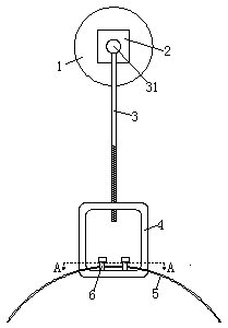
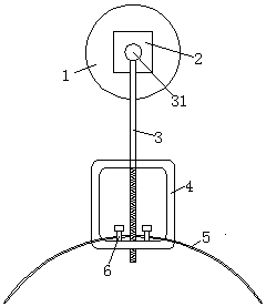
[0036] Such as figure 2 As shown, the structure of the retraction device for embedded teeth in this embodiment is basically the same as that in Embodiment 1, the difference is that the traction ring 4 is provided with a second threaded hole 42 at the end opposite to the first threaded hole 41, and the The first and second threaded holes are located on the same straight line, and the connecting rod 3 can be connected with the first and second threaded holes in turn, such as image 3 with Figure 4 shown.

[0037] In this embodiment, the traction ring 4 is provided with two connecting nails 6 inside the end where the second threaded hole 42 is provided, and the two connecting nails 6 are symmetrically arranged on both sides of the second threaded hole 42 . The connecting nail 6 is used to connect with the arch wire 5 of the auxiliary arch, combined with Figure 5 As shown, one end of the arch wire 5 penetrates from the side of the traction ring 4, passes through the side of ...

Embodiment 3

[0042] Such as Figure 9 As shown, the structure of the traction device for embedded teeth of this embodiment is basically the same as that of Embodiment 2, except that the traction ring 4 includes a ring body 43 and a cylinder 44 fixed at one end of the ring body 43, and the cylinder body 44 is provided with the internal thread that matches with connecting rod 3. The ring body 43 is fixed with a connecting nail 6 inside the end opposite to the cylinder 44. In this embodiment, only one connecting nail 6 is required, so the width of the traction ring 4 can be further reduced, which is convenient for use.


PUM


Abstract

The invention relates to an impacted tooth traction apparatus. The traction apparatus comprises a bottom plate, a fixed block, a connecting rod and a traction ring, wherein the bottom plate is used for connecting with an impacted tooth, the fixed block is fixedly arranged on one end of the bottom plate, one end of the connecting rod is connected with the fixed block, the other end of the connecting rod is provided with threads, and is connected with the traction ring through the threads, the traction ring is rotated, and the traction ring moves along the connecting rod toward or away from thebottom plate. The traction apparatus has a simple structure, a high bonding success rate, and is convenient for the strength traction of the impacted tooth in the three dimensional direction by usingan arch-wire or a rubber chain.

Description

technical field [0001] The invention relates to a traction device for an ambush tooth, which belongs to the technical field of orthodontic tools. Background technique [0002] Impacted tooth is a relatively common intractable disease in orthodontics, and its prevalence rate can reach 2%. Among them, the incidence of ambushed impacted canines is high, which can not only lead to malocclusion, but also significantly affect the appearance, and may also oppress the roots of adjacent teeth, leading to root absorption, and cysts may also form in secondary infection, affecting the physical and mental health of patients. Accurate treatment of impacted canines is of great significance. [0003] At present, accurate three-dimensional traction for impacted teeth has always been a difficult point in clinical practice. Accessories for traditional impact tooth traction are usually off-the-shelf, such as lingual buckles, brackets, or other devices. Because the shape of the accessory base...

Claims


Application Information

Patent Timeline
IPC IPC(8): A61C7/00A61C7/12A61C7/16
CPCA61C7/00A61C7/12A61C7/16
Inventor 韩磊李佳岭李煌季骏
Owner NANJING STOMATOLOGICAL HOSPITAL
Why Eureka
Try Eureka