Methods and apparatus for 3D route planning through hollow organs

a hollow organ and route planning technology, applied in the field of medical imaging, can solve the problems of difficult mental defining the 3d relationship between the endoscope, the airway, and the target roi as depicted in the mdct data and the video feed, and difficult to determine the appropriate route through the organ to the target location

Active Publication Date: 2008-07-31
PENN STATE RES FOUND
View PDF5 Cites 163 Cited by
  • Summary
  • Abstract
  • Description
  • Claims
  • Application Information

AI Technical Summary

Benefits of technology

[0025]The information provided may include anatomical constraints that define locations or organs to avoid; anatomical constraints that confine the route within specific geometric locations; or a metric for selecting the most appropriate route. For example, the metric may devine the closest route to the ROI such that the route satisfies all applicable anatomical, device, and procedural constraints.

Problems solved by technology

The navigation through the organ may be virtual—solely within data derived from the 3D image, or it may be by a device, such as an endoscope, moving through the organ in a follow-on live procedure.1,3,5-7 In each circumstance, an appropriate route through the organ to the target location is often difficult to determine.
Defining such a route to suspect peripheral nodules in the chest can be especially challenging because: (1) several airway generations from the trachea need to be traversed, (2) the airway cross-sections are obliquely oriented relative to the given axial-plane data, and (3) the airway tree continually bifurcates as a route is traversed.12-13
Even in the best circumstances, mentally defining the 3D relationships between the endoscope, airways, and target ROI as depicted in the MDCT data and the video feed is difficult.
Respiratory motion, coughing, and the inability to view ROIs situated beyond the airway walls make the task even more challenging.
However, even with the additional information provided by the centerline-analysis and segmentation computations, manual route definition is still a challenging task.
However, it is seen in the sagittal view that this route is inappropriate.
Even with the assistance of 2D, 3D), and quantitative visualization techniques such as thin-slab visualizations, 3D airway, surface, and ROI renderings, and quantitative plots of airway measurements, manual route planning is difficult.25-28 Centerline-analysis techniques may produce over 200 distinct paths through the major airways.
Thus, the extracted paths through the airways can be insufficiently defined to reach a particular ROI.
Thus, manually searching through a large number of paths to find an acceptable route to an ROI is tedious.
Because the method does not utilize the 3D medical image and instead relies on the surfaces to represent the airway tree, sections of the organ may not be accurately modeled due to imperfections in segmentation techniques.
However, the target location is limited to be within the original airway-tree segmentation and is required to be known a priori.
However, in regions of poor image quality or weakly defined airways, the user may be required to provide multiple “seed points” to achieve acceptable results.
This method, while defining paths robustly, does not fully achieve automated route-planning.
However, the existence or accuracy of this correlation is not guaranteed.
This method may not be able to determine adequate routes if the organ is difficult to segment, as is often the case in airway trees.
These costs correspond to the detrimental effects of different surgical events, such as incisions and contact.
However, there seems to be no method that finds viable paths to precisely-defined ROIs in volumetric images while taking into account the physical properties of the endoscopic device, anatomical constraints, and procedure-specific constraints, and that also allows for the extension of routes beyond the segmentation, if required.

Method used


Image

  • Methods and apparatus for 3D route planning through hollow organs
  • Methods and apparatus for 3D route planning through hollow organs
  • Methods and apparatus for 3D route planning through hollow organs

Examples


Embodiment Construction

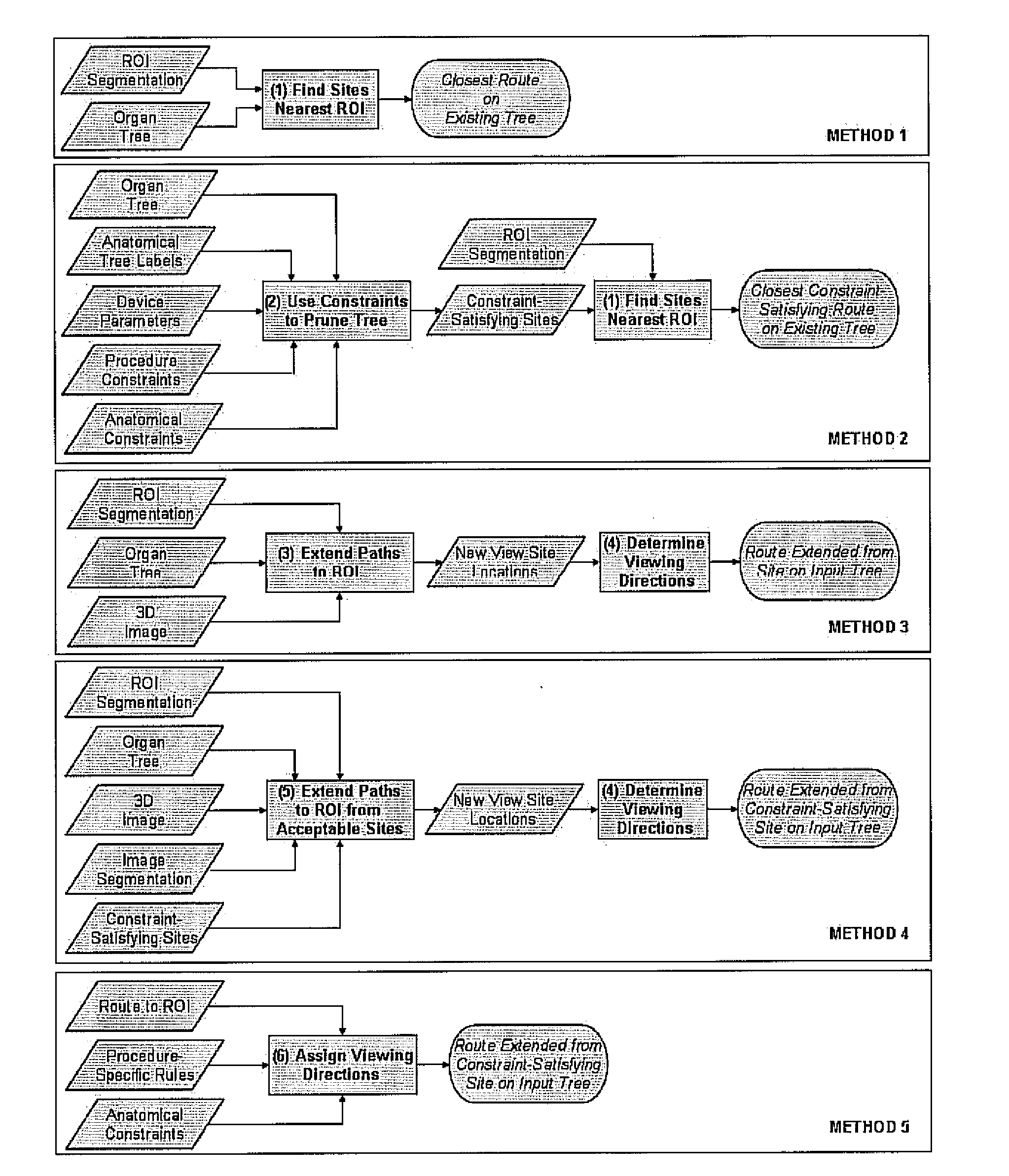
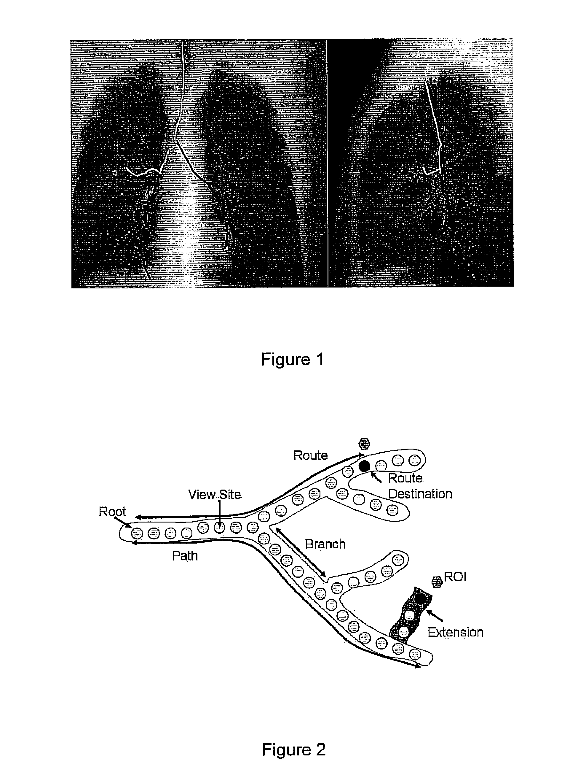
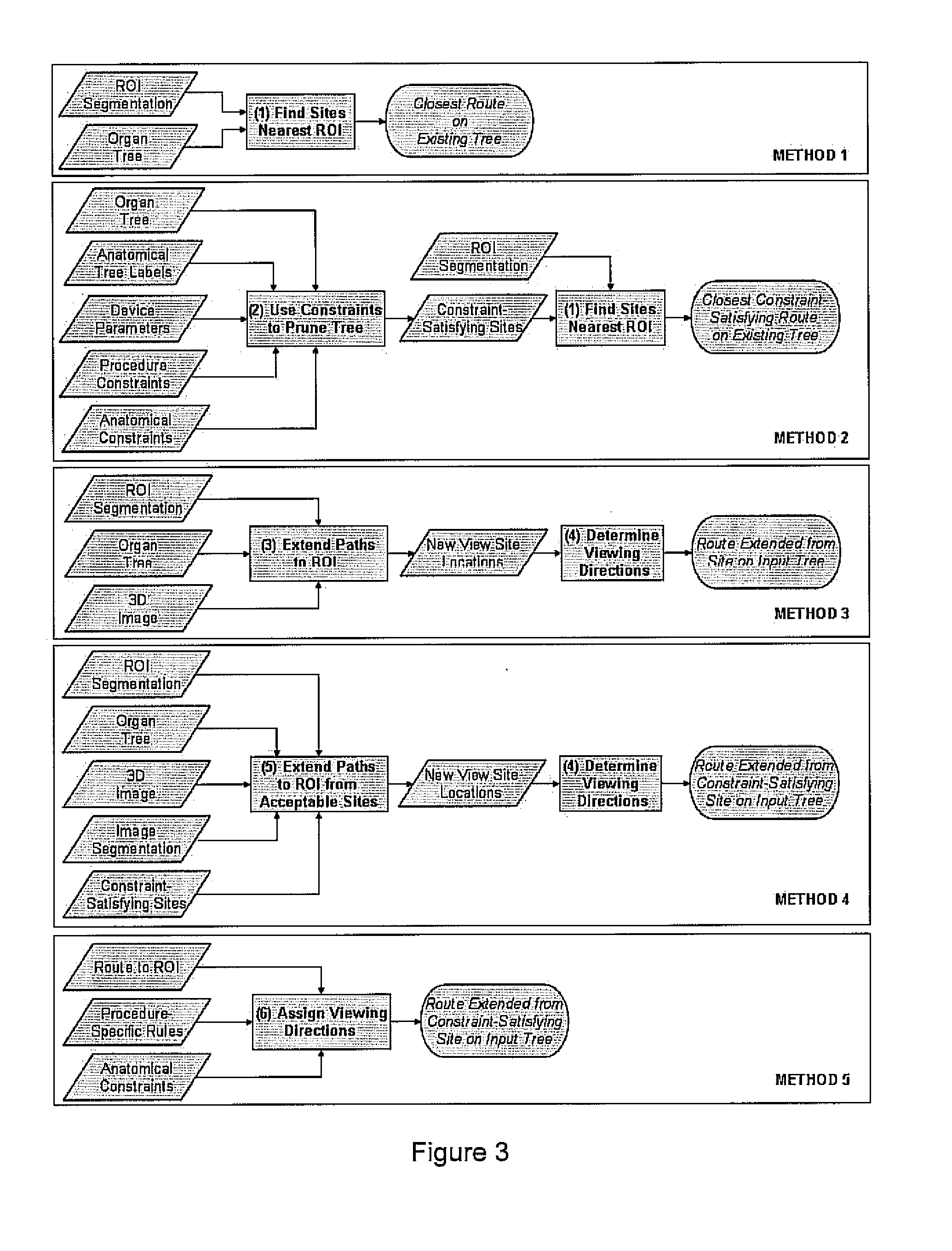
[0044]We have developed methods for automated route-planning, drawing upon 3D images, that assists follow-on navigation through hollow branching organs. In our work, we focus on MDCT images of the chest wherein the goal is to navigate through the airway tree, often for the treatment and assessment of lung cancer. In this paradigm, we restrict the routes to be contained within a patient-specific model of a tubular organ such as the colon or airway tree.

[0045]This invention resides in automated techniques for 3D route planning that: (1) locate the closest paths to a target ROI and (2) extend an incomplete path, if necessary, so that it reaches the ROI. Given a 3D medical image, our methods take as input: (1) precisely defined ROIs; (2) a segmentation of the branching organ through with the endoscopic device will navigate; (3) centerlines (paths) through the segmented organ; and (4) parametric description of the endoscopic device.

[0046]We use existing methods for branching-organ segmen...


PUM


Abstract

Methods and apparatus assist in planning routes through hollow, branching organs in patients to optimize subsequent endoscopic procedures. Information is provided about the organ and a follow-on endoscopic procedure associated with the organ. The most appropriate navigable route or routes to a target region of interest (ROI) within the organ are then identified given anatomical, endoscopic-device, or procedure-specific constraints derived from the information provided. The method may include the step of modifying the viewing direction at each site along a route to give physically meaningful navigation directions or to reflect the requirements of a follow-on live endoscopic procedure. An existing route may further be extended, if necessary, to an ROI beyond the organ. The information provided may include anatomical constraints that define locations or organs to avoid; anatomical constraints that confine the route within specific geometric locations; or a metric for selecting the most appropriate route. For example, the metric may define the closest route to the ROI such that the route satisfies all applicable anatomical, device, and procedural constraints.

Description

REFERENCE TO RELATED APPLICATION[0001]This application claims priority from U.S. Provisional Patent Application Ser. No. 60 / 887,472, filed Jan. 31, 2007, the entire content of which is incorporated herein by reference.GOVERNMENT SPONSORSHIP[0002]This work was partially supported by Grant No. CA074325 from the National Cancer Institute of the NIH. The US Government may have rights in this invention.FIELD OF THE INVENTION[0003]This invention relates generally to medical imaging and, in particular, to a system and method for three-dimensional (3D) route planning and extension to assess hollow, branching organs in patients.BACKGROUND OF THE INVENTION[0004]Physicians routinely utilize three-dimensional (SD) medical imaging methods to assess hollow, branching organs in patients Examples of such organs include the liver vasculature, heart vasculature, and the airways of the chest.1-3 Examples of 3D medical imaging modalities used to examine these organs are multidetector computed tomograph...

Claims


Application Information

Patent Timeline
Patent Type & Authority Applications(United States)
IPC IPC(8): A61B6/03
CPCA61B2019/505A61B2019/507G06T19/003G06T2210/41G06T2207/30061A61B2034/105A61B2034/107A61B34/10A61B1/000096A61B1/00045A61B1/2676A61B6/032A61B6/466A61B6/469
Inventor HIGGINS, WILLIAM E.GIBBS, JASON D.
Owner PENN STATE RES FOUND
Why Eureka
Try Eureka