
System and Methods For Performing Spinal Fixation

Active Publication Date: 2008-07-31
NUVASIVE
View PDF75 Cites 126 Cited by
  • Summary
  • Abstract
  • Description
  • Claims
  • Application Information

AI Technical Summary

Benefits of technology

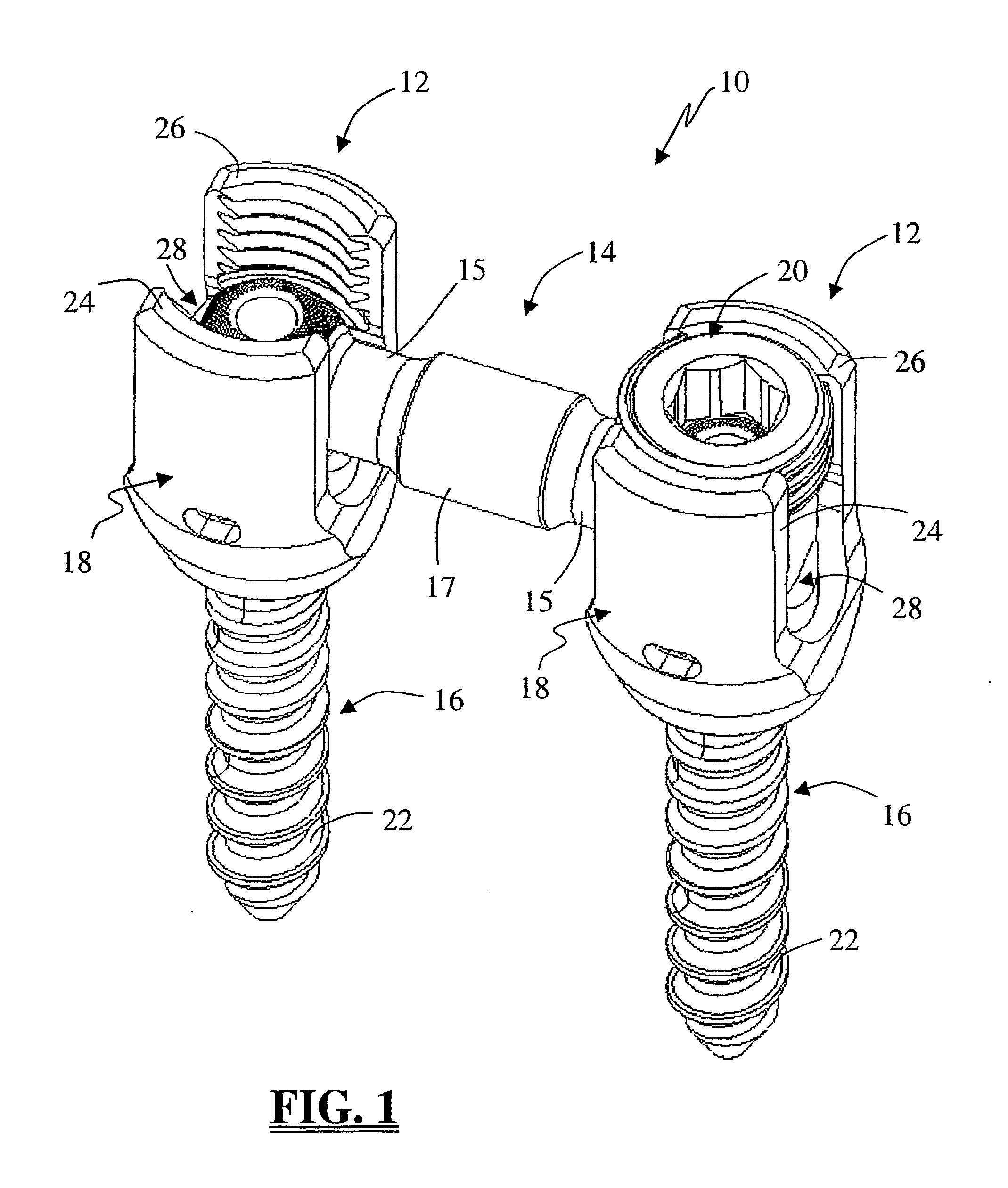
[0008]In an important aspect, the elongated connecting members are equipped with shaped ends dimensioned to be received within correspondingly shaped receiving areas within the pedicle screw housing. As will be described in detail herein, the shaped ends of the connecting members are advantageous in terms of facilitating the ease of introduction into, and engagement within, the pedicle screw housing. The shaped ends of the connecting members are also advantageous when employed with multi-axial pedicle screws by allowing a surgeon to perform “instrument free” compression and / or distraction of the vertebral bodies by rotating the pedicle screw housing about the shaped end of the connecting member. This is accomplished via the use of a minimally disruptive introduction system forming part of the present invention.
[0009]The minimally disruptive introduction system of the present invention includes a guide assembly for guiding (as a first step) each pedicle screw into the respective vertebra and (as a second step) guiding the connecting element such that the shaped ends are disposed within the correspondingly shaped receiving area of the pedicle screw housings. The minimally disruptive introduction system may also include a variety of additional instruments for facilitating the introduction of the pedicle screws (e.g., a spinal access needle (e.g. Jamshidi needle), a guide wire (e.g. K-wire), a pedicle screw driver, a cannulated tap, etc. . . . ), instruments for locking the connecting member to the pedicle screws (e.g., a locking element driver, etc. . . . ), and instruments for insulating the various components of the spinal fixation system and / or introduction system during optional EMG-based pedicle integrity testing during pilot hole formation, preparation, and screw introduction. The minimally disruptive introduction system is advantageous in that it provides the ability to access the spinal target site with a generally small incision and with minimal tissue disruption.

Problems solved by technology

Existing system are limited in their ability to be used for percutaneous procedures and, of those available, various drawbacks exist.

Method used


Image

  • System and Methods For Performing Spinal Fixation
  • System and Methods For Performing Spinal Fixation
  • System and Methods For Performing Spinal Fixation

Examples


Embodiment Construction

[0049]Illustrative embodiments of the invention are described below. In the interest of clarity, not all features of an actual implementation are described in this specification. It will of course be appreciated that in the development of any such actual embodiment, numerous implementation-specific decisions must be made to achieve the developers' specific goals, such as compliance with system-related and business-related constraints, which will vary from one implementation to another. Moreover, it will be appreciated that such a development effort might be complex and time-consuming, but would nevertheless be a routine undertaking for those of ordinary skill in the art having the benefit of this disclosure. The systems disclosed herein boast a variety of inventive features and components that warrant patent protection, both individually and in combination.

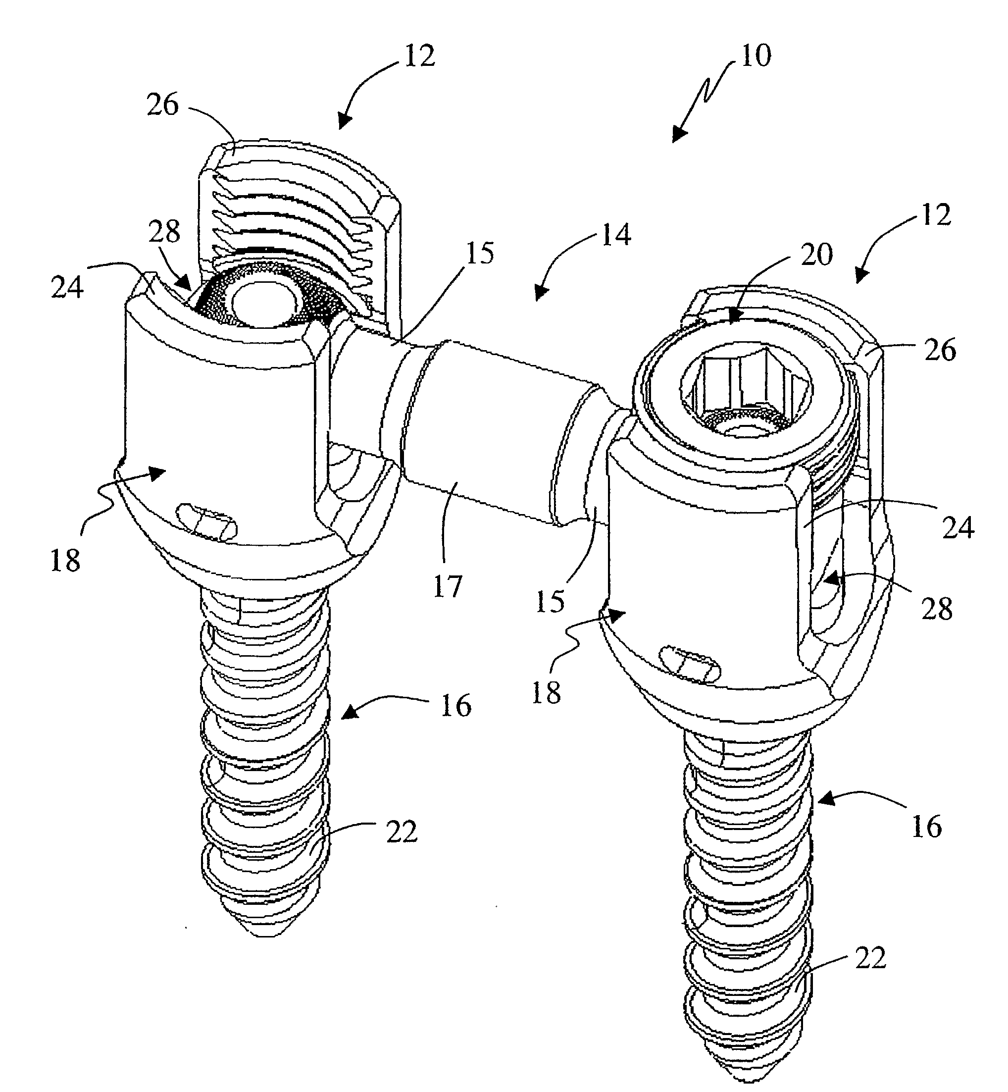
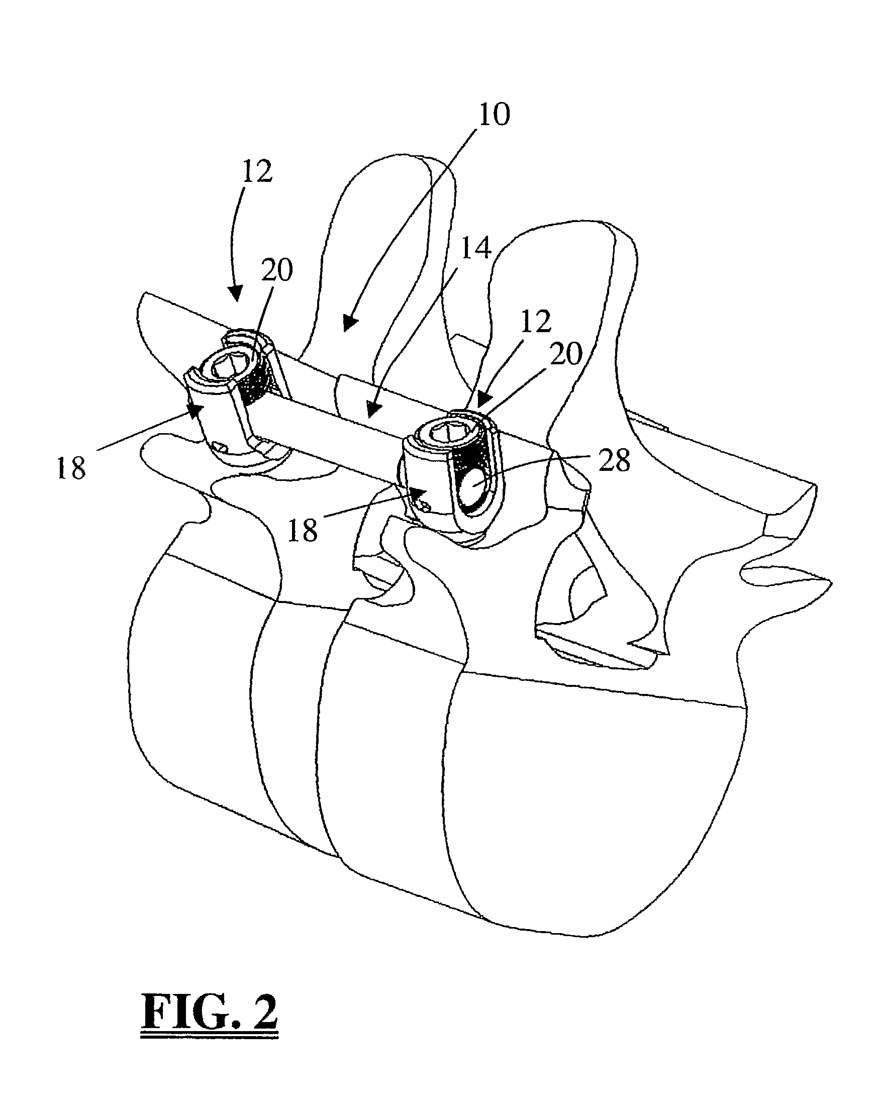
[0050]FIGS. 1 and 2 illustrate a spinal fixation system 10 according to the “single level” embodiment of the present invention. ...


PUM


Abstract

A system and methods for performing spinal fixation, including a spinal fixation system with at least rod member having shaped ends, at least two pedicle screws capable of receiving the shaped ends of the rod member, and a system for percutaneously introducing the rod member and pedicle screws to perform spinal fixation.

Description

CROSS REFERENCE TO RELATED APPLICATIONS[0001]This is an International Patent Application claiming the benefit of priority under 35 USC 119(e) of commonly owned and co-pending U.S. Provisional Patent Application No. 60 / 608,476 entitled “System and Method for Performing Spinal Fixation,” filed Sep. 8, 2004, the entire contents of which is hereby expressly incorporated by reference into this disclosure as if set forth fully herein.BACKGROUND OF THE INVENTION[0002]I. Field of the Invention[0003]The present invention relates to medical devices and methods generally aimed at spinal surgery. In particular, the disclosed system and associated methods relate to performing spinal fixation.[0004]II. Discussion of the Prior Art[0005]Fixation systems are often surgically implanted into a patient to aid in the stabilization of a damaged spine or to aid in the correction of other spinal geometric deformities. Spinal fixation systems are often constructed as a framework stabilizing a particular sec...

Claims


Application Information

Patent Timeline
IPC IPC(8): A61B17/58A61B17/56
CPCA61B17/7004A61B17/7005A61B17/7011A61B17/7032A61B17/7037A61B2017/0256A61B17/708A61B17/7085A61B17/7091A61B17/7092A61B17/7076
Inventor COPP, MATTHEWCAMPBELL, CHRISTOPHER M.CORNWALL, G. BRYANDASSO, ERICPHILLIPS, FRANK M.
Owner NUVASIVE
Learn More