Methods to monitor system sensor and actuator health and performance

a sensor and actuator technology, applied in the direction of survey, instruments, borehole/well accessories, etc., can solve the problems of job failure, operator is liable to be unaware of impending or immediate failures, affecting job performance, etc., and achieve the effect of reducing operator errors

Active Publication Date: 2008-07-31
HALLIBURTON ENERGY SERVICES INC
View PDF7 Cites 24 Cited by
  • Summary
  • Abstract
  • Description
  • Claims
  • Application Information

AI Technical Summary

Benefits of technology

[0011]By using the available sensor data in conjunction with a model of the system dynamics, the controller can be designed to estimate sensor and actuator failures and update the operator through the interface. The controller can also be designed with system intelligence which can be used to help the operator perform the job and reduce operator error.

Problems solved by technology

These failures can affect job performance and lead to job failure.
This means an operator is liable to be unaware of impending or immediate failures, and requires a higher degree of knowledge on the part of an operator.
This information is compared, and discrepancies indicate that some sensor of the system may be failing or outside preferred operating conditions.

Method used


Image

  • Methods to monitor system sensor and actuator health and performance
  • Methods to monitor system sensor and actuator health and performance
  • Methods to monitor system sensor and actuator health and performance

Examples


Embodiment Construction

[0024]The numerous innovative teachings of the present application will be described with particular reference to the presently preferred embodiment (by way of example, and not of limitation).

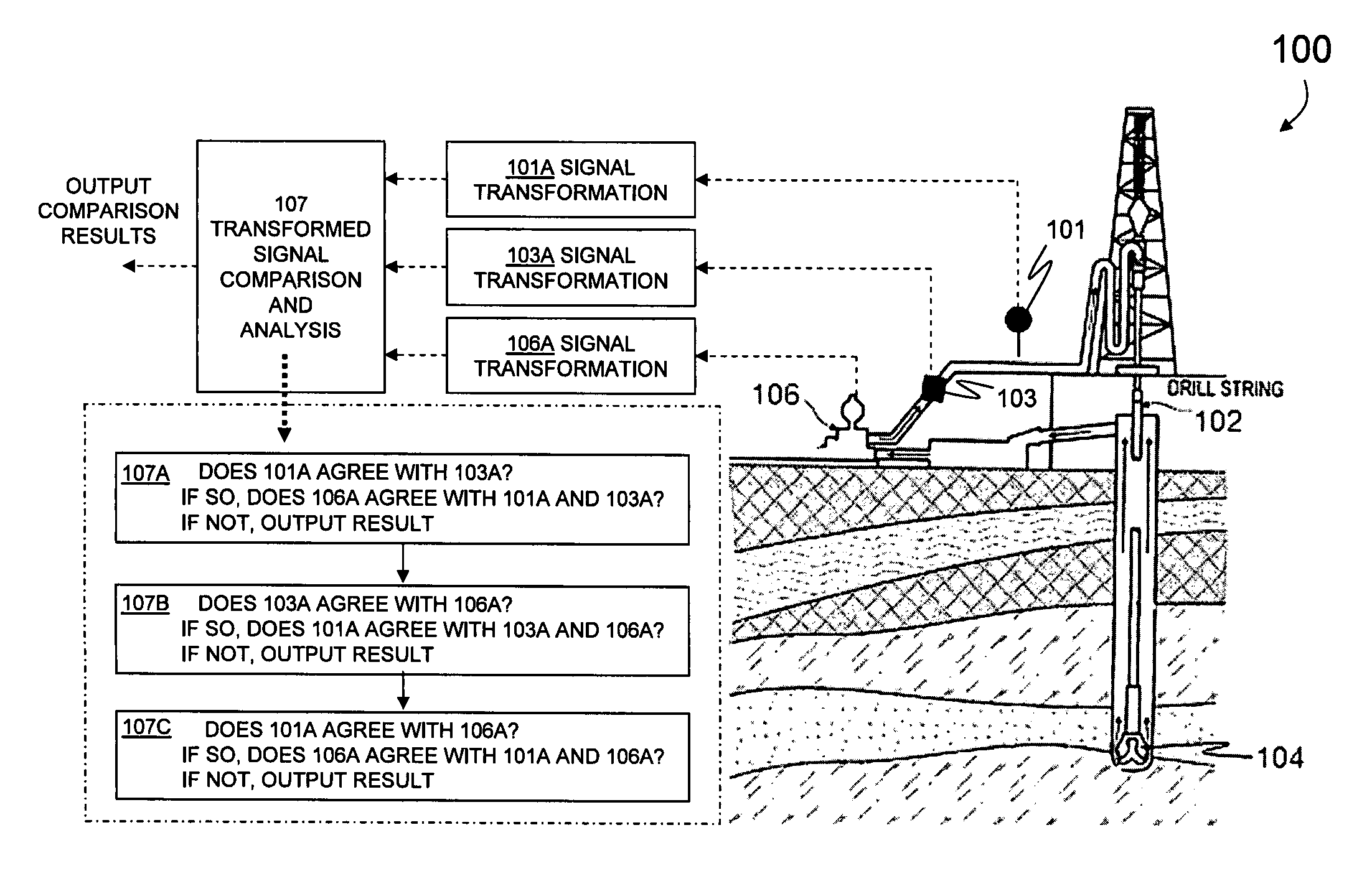
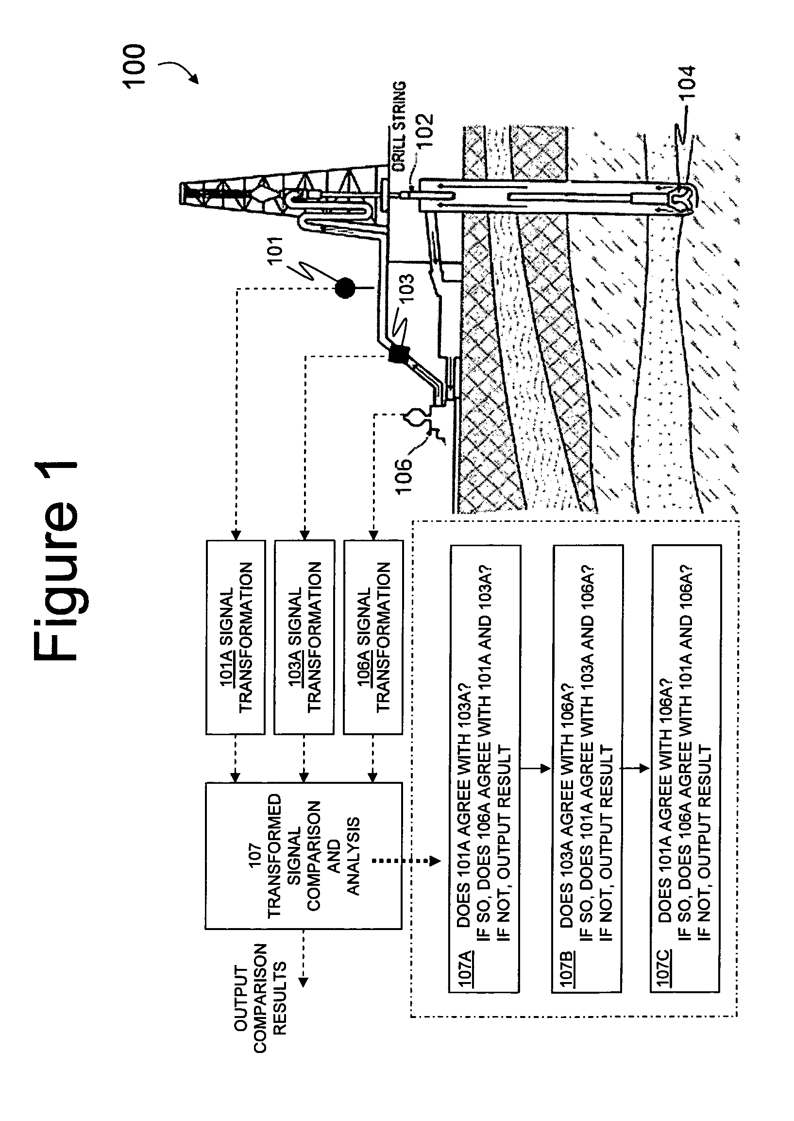
[0025]FIG. 1 shows an example system in which embodiments of the present innovations can be implemented. This example shows an oilfield drilling system 100, including a drill string 102, and downhole tool 104. Drilling system 100 also includes a pump system 106 which controls insertion of materials downhole, such as drilling mud for cooling and removal of debris, or other slurries (such as sand and water combinations) for various tasks.

[0026]In a preferred embodiment, the drilling system 100 includes sensors such as flow meter 101 that monitor and characterize the performance of various subsystems. This information is used, often by an operator, but also by automated systems, to determine when performance is outside desired bounds or failure occurs or is about to occur.

[0027]Specifically, FIG. ...


PUM


Abstract

A method for assessing health and performance of a system. In one example, the system comprises subsystems (preferably physically coupled subsystems), at least some of which are characterizable by transmitted signals. Some of these signals are transformed into a comparable form and compared, so as to identify signals that are outside of operating bounds.

Description

BACKGROUND AND SUMMARY OF THE INVENTION[0001]The following applications filed concurrently herewith are not necessarily related to the present application, but are incorporated by reference herein in their entirety: “Methods for Managing Flow Control Valves in Process Systems” (U.S. patent application Ser. No. ______, filed simultaneously with the effective filing date of the present application, Attorney Docket Number HES-2005-IP-019666U3); “Systems for Managing Flow Control Valves in Process Systems” (U.S. patent application Ser. No. ______, filed simultaneously with the effective filing date of the present application, Attorney Docket Number HES-2005-IP-019666U4); and “Systems for Monitoring Sensor and Actuator Health and Performance” (U.S. patent application Ser. No. ______, filed simultaneously with the effective filing date of the present application, Attorney Docket Number HES-2005-IP-019666U2).[0002]The present application relates to monitoring complex systems such as automa...

Claims


Application Information

Patent Timeline
Patent Type & Authority Applications(United States)
IPC IPC(8): G06F19/00
CPCE21B41/00E21B47/00E21B44/00
Inventor DYKSTRA, JASON D.
Owner HALLIBURTON ENERGY SERVICES INC
Why Eureka
Try Eureka