Buffer arrangement

a buffer arrangement and buffer technology, applied in the direction of conveyors, conveyor parts, metal working devices, etc., can solve the problem of inability to change the order of workpiece carriers in the buffer, and achieve the effect of reducing the slope of the slide path, maximizing the storage capacity of the buffer arrangement, and reducing static friction

Inactive Publication Date: 2008-08-07
LANG TECHN
View PDF6 Cites 26 Cited by
  • Summary
  • Abstract
  • Description
  • Claims
  • Application Information

AI Technical Summary

Benefits of technology

[0009]The slide path includes, preferably at least, one slide track. But it may also include several, for example, two slide tracks which extend for example in parallel relationship and which fully support the load of the workpiece carriers. The slide tracks may have guide tracks associated therewith which prevent a sliding off of the clamping bolts from the slide tracks.
[0010]In a preferred embodiment, the slide path is coil-like spiraled. In this way a high storage capacity is obtained. In addition, the coil-like spiraled slide path can be supported by a central column which includes radial arms for supporting the slide track. This provides for a simple and clear design. An operator has easy access to the workpiece carriers on the slide track. As a result, a manual interference into the manufacturing process is always possible without causing interruptions of the whole manufacturing process.
[0012]In a preferred embodiment, a vibration generator is associated with the slide path. This minimizes the static friction between the respective slide surfaces of the workpiece carrier and the slide path. This permits a reduction of the slope of the slide path so that the storage capacity of the buffer arrangement can be maximized.

Problems solved by technology

An order change of the workpiece carriers in the buffer is not possible.

Method used


Image

  • Buffer arrangement
  • Buffer arrangement
  • Buffer arrangement

Examples


Embodiment Construction

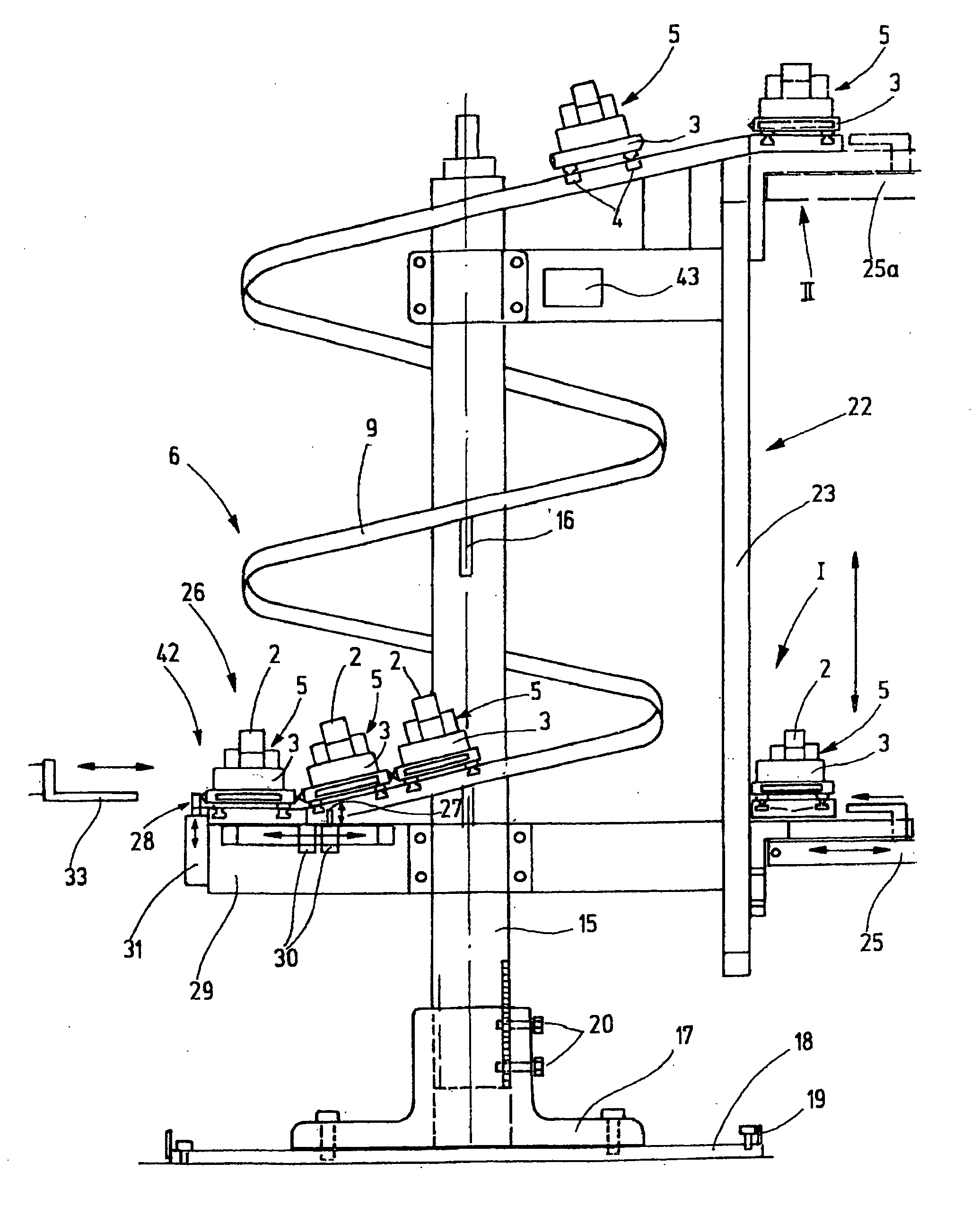
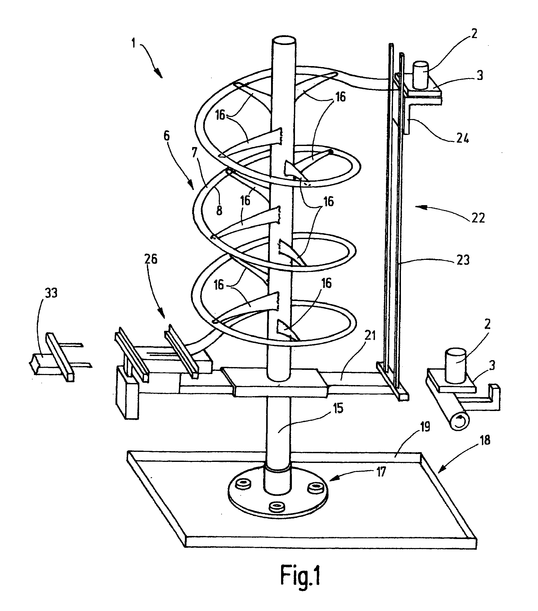
[0022]FIG. 1 shows a buffer arrangement 1 which serves as a buffer specifically for workpieces 2, which are clamped onto workpiece carriers 3. In the figures, the workpiece is simply shown as a cylinder. However, the workpiece may have any shape.

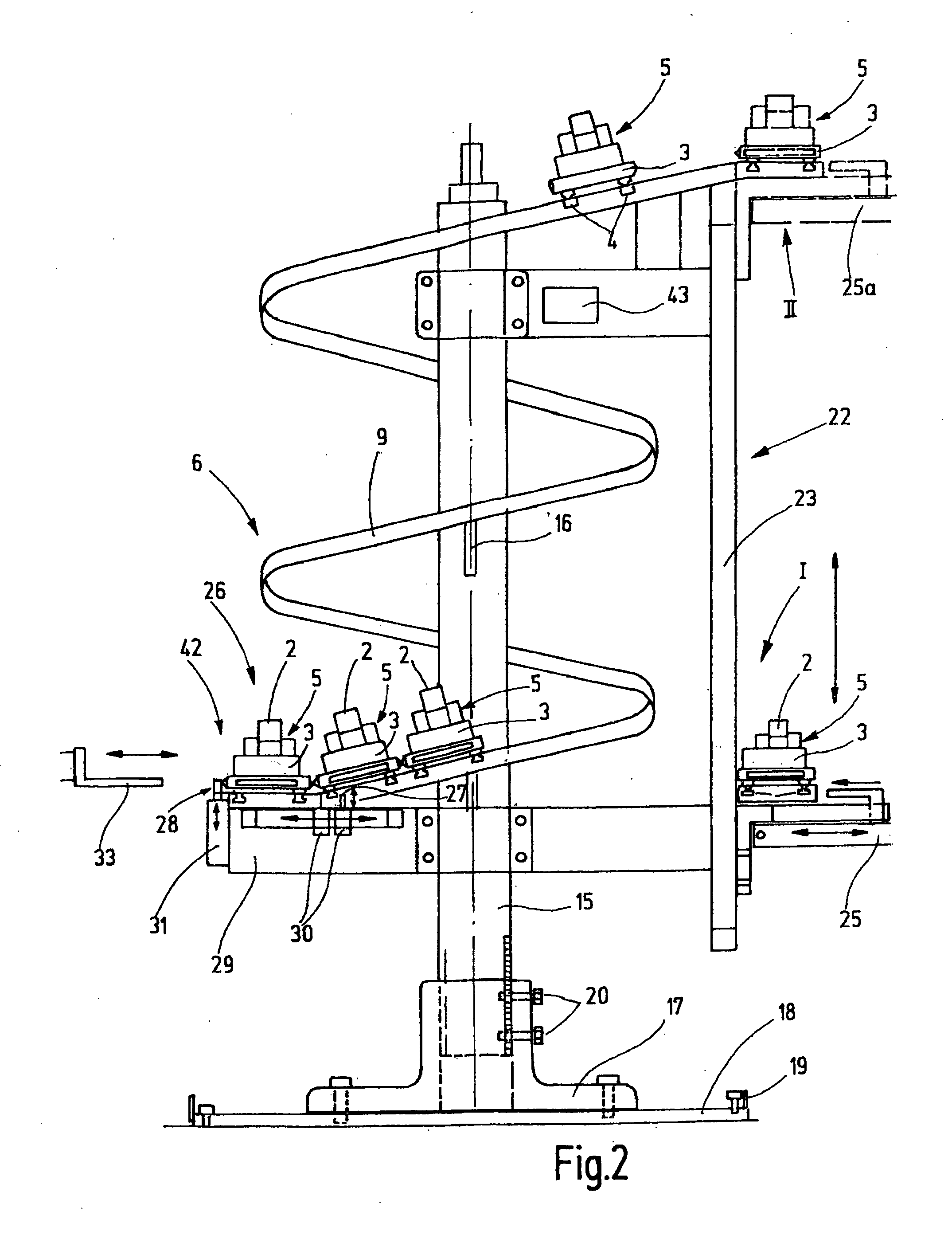
[0023]The workpiece carrier 3 consists essentially of a oblong support plate which is oriented horizontally when used, for example, a rectangular plate which is provided at its bottom side with several, for example, four clamping bolts 4 as shown in FIGS. 2, 3, and 4. The clamping bolts 4 are used to position and clamp the workpiece carrier 3 in the machining tools during machining of a respective workpiece 2. For clamping the workpiece to the carrier 3, the carrier 3 is provided at its top side with a clamping arrangement 5 which includes one or more clamping claws which can be locked in clamping position.

[0024]The buffer arrangement 1 comprises for storing the workpiece carriers 3 a sloped slide path 6 as shown in FIGS. 1 and 2. The slope ...


PUM

PropertyMeasurementUnit
static frictionaaaaaaaaaa
timeaaaaaaaaaa
shapeaaaaaaaaaa

Abstract

The buffer arrangement according to the invention comprises a slide path (6) for a workpiece carrier (3). Preferably, the slide path (6) is coil-like wound and supported on a central column (15). The slide path (6) comprises preferably at least one slide track (7, 8) and possibly one or several guide tracks (9, 10). The workpiece carriers (3) slide on the slide tracks (7, 8) preferably with the front sides of the centering and clamping bolts disposed on the slide tracks (7, 8).

Description

CROSS-REFERENCE TO RELATED APPLICATION[0001]This application claims the priority benefits of German Application No. 10 2007 005 994.0 filed Feb. 7, 2007.BACKGROUND OF THE INVENTION[0002]The invention resides in a buffer arrangement for workpiece carriers.[0003]In the automatic or partially automatic manufacture, workpieces are often supported by workpiece carriers on which they are moved through the whole manufacturing process or at least a good part thereof without being disconnected from the carrier. Since the machining times may be different in different machine tools as to provide for a certain buffer amount, it may be expedient to provide buffer arrangements which may be arranged ahead of, or after, individual machine tools or which may also be arranged independently for an interim storage of workpieces clamped onto workpiece carriers. These buffer arrangements however should require only little space. Furthermore, they should be simple and reliable and clear in their layout.[0...

Claims


Application Information

Patent Timeline
Patent Type & Authority Applications(United States)
IPC IPC(8): B23Q7/08
CPCB65G21/18B65G47/5109Y10T29/53543B65G2201/0267Y10T29/53478B65G47/8884
Inventor LANG, GUNTER
Owner LANG TECHN
Why Eureka
Try Eureka