
Insulated block with non-linearthermal paths for building energy efficient buildings

a technology of energy-efficient buildings and insulated blocks, which is applied in the direction of passive houses, walls, manufacturing tools, etc., to achieve the effects of extending and increasing the thermal mass properties, increasing insulation values, and effectively creating an energy-efficient, flood-resistant, hurricane-resistant hom

Inactive Publication Date: 2008-08-07
FISCHER SCOTT
View PDF9 Cites 40 Cited by
  • Summary
  • Abstract
  • Description
  • Claims
  • Application Information

AI Technical Summary

Benefits of technology

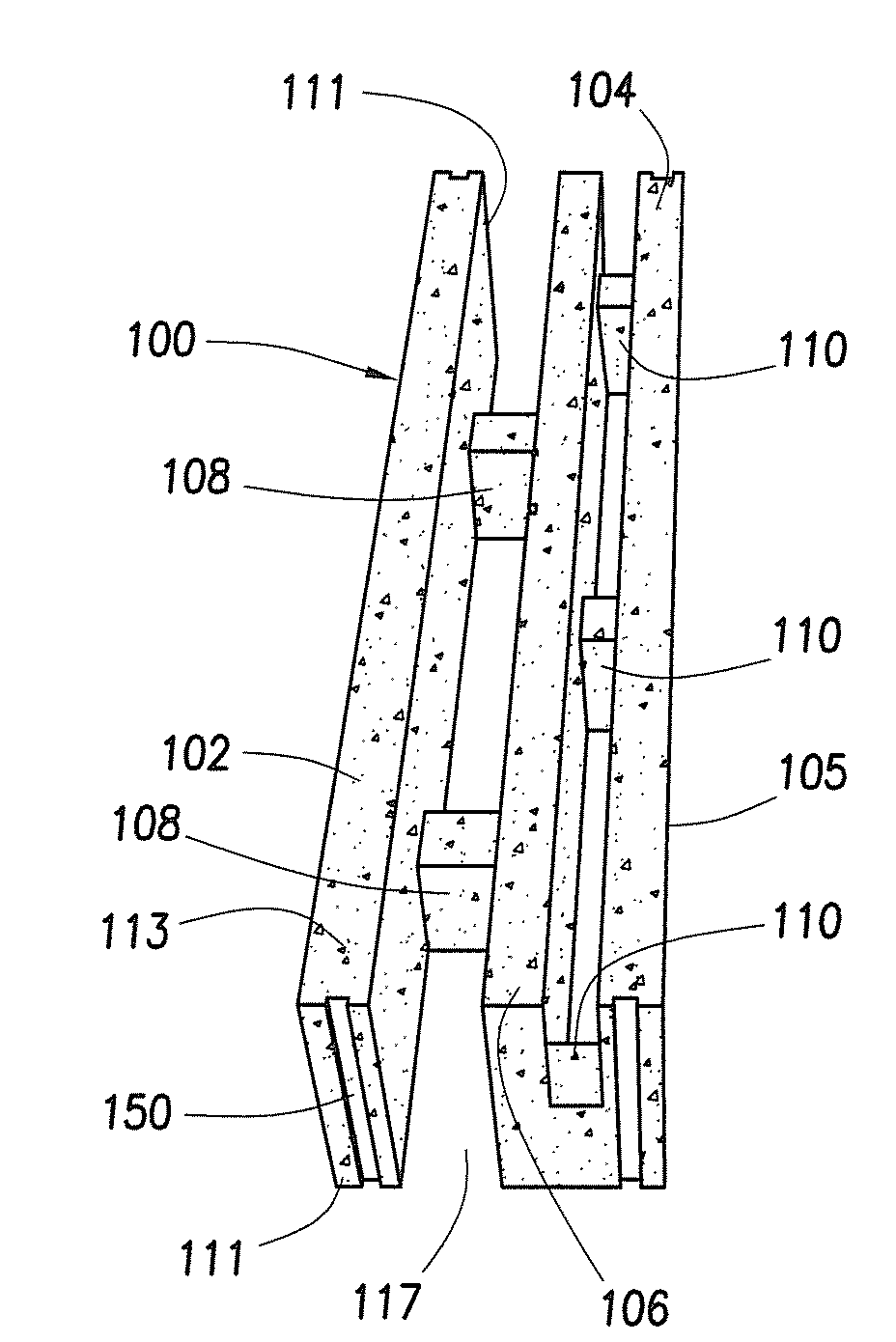
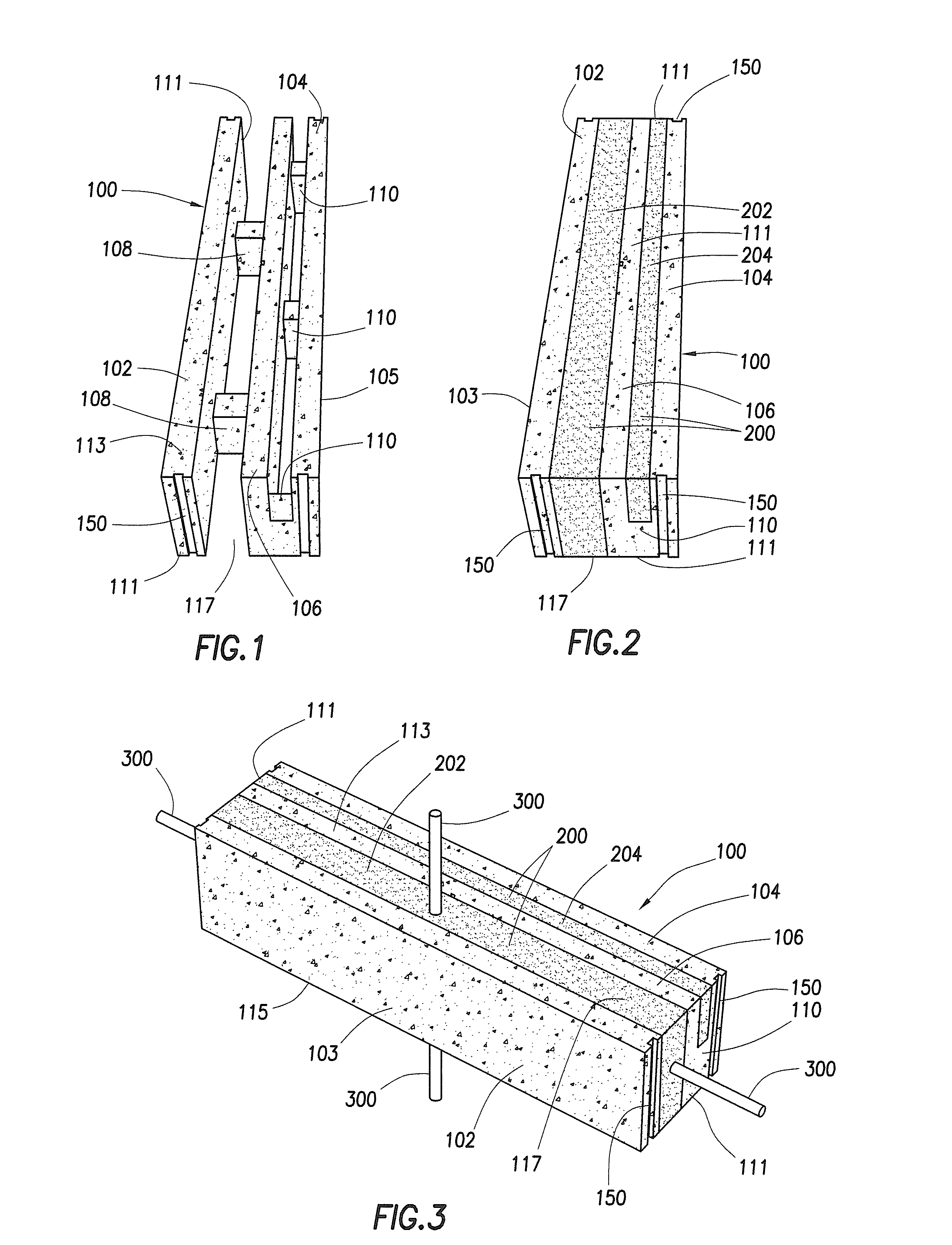
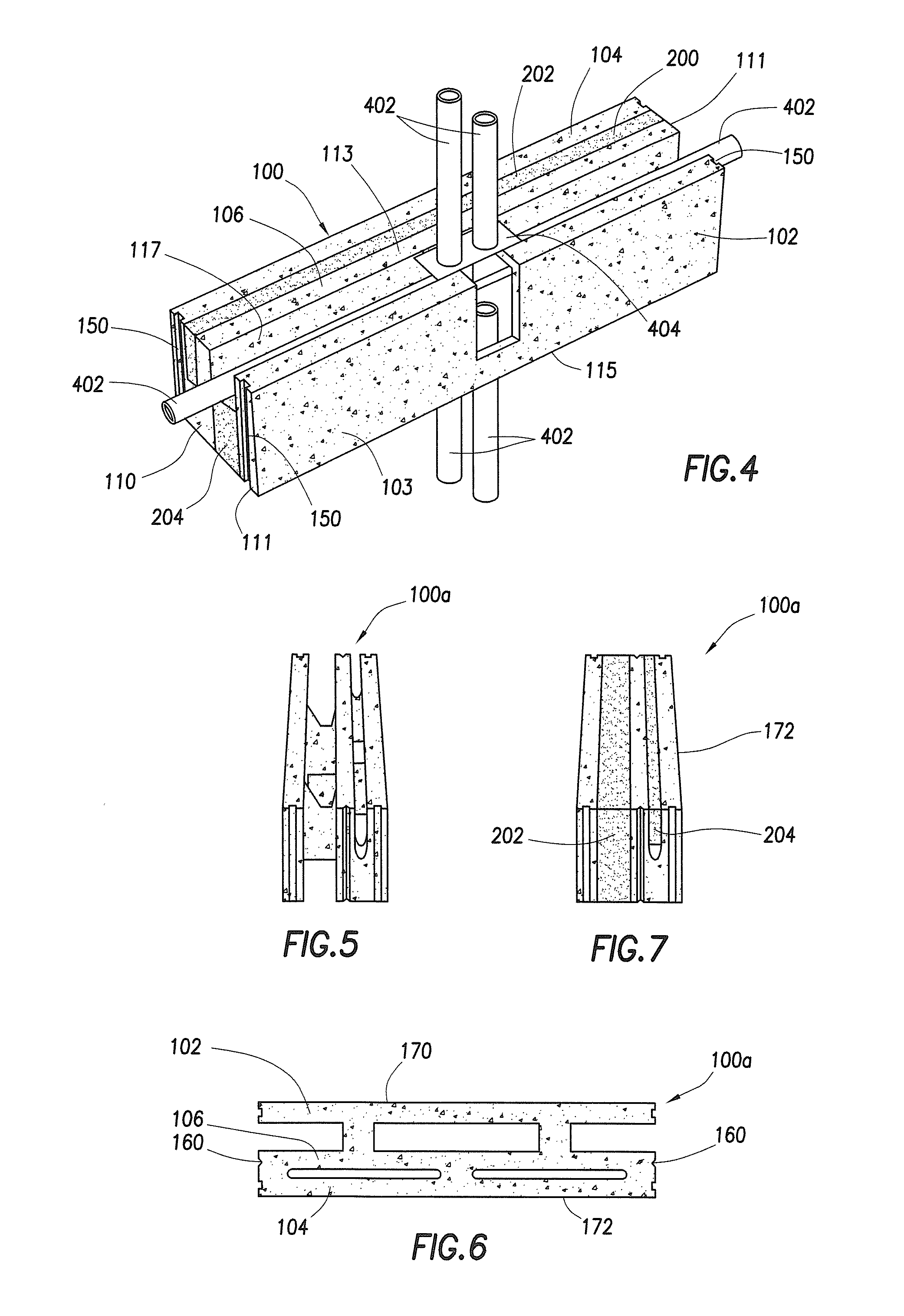
[0006]The block incorporates engineering designs that create non-linear thermal paths across the block, thereby extending and increasing the thermal mass properties by offsetting and restricting the cross webbing of the block. Details include electrical, rebar and grout reinforcement systems, post-tension systems, dry stacked or mortared, foam filled or not. Typically, foam fills a majority of the interior and all of the exterior cavities, increasing insulation values, and filling voids creating a relatively solid unit. The system has no wood or sheetrock requirements. As an inorganic block wall system it is not food or fuel for mold, termites, ants, or fire. As used herein, “inorganic” means being or composed of matter other than plant or animal. Being solid and free of voids there are no significant spaces for air to fuel fire, water to support mold growth, or places for insect habitation. The block is impervious to flood water damage and as a heavy weight system, the block, or the building, would not float. Combined with a quality roof, storm shutters, and a generator, the system can be used to effectively create an energy efficient, floodable, hurricane resistant home with an option not to evacuate. The design negates the need for abandoning and or gutting walls after a flood.

Problems solved by technology

As an inorganic block wall system it is not food or fuel for mold, termites, ants, or fire.

Method used


Image

  • Insulated block with non-linearthermal paths for building energy efficient buildings
  • Insulated block with non-linearthermal paths for building energy efficient buildings
  • Insulated block with non-linearthermal paths for building energy efficient buildings

Examples


Embodiment Construction

[0042]As used herein, the words “comprise,”“has,” and “include” and all grammatical variations thereof are each intended to have an open, non-limiting meaning that does not exclude additional elements or steps.

[0043]In general, as used herein, words describing relative orientation or position, such as “inward,”“outward,”“head” or “end,”“top” and “bottom,” and similar terms regarding various elements in the views of the drawing are with respect to the perspective of a block as it is to be normally used in the position as shown in FIGS. 1-4, wherein an electrical outlet box would normally be positioned as shown in FIG. 4 toward the interior side of a wall made with the blocks. It is to be understood, of course, that a block could be used in an upside down orientation, as in the header for a window or door in a wall formed of the blocks.

[0044]The same reference numerals or used for similar parts in the various embodiments of the invention and as shown in the Figures of the drawing.

[004...


PUM

PropertyMeasurementUnit
Sizeaaaaaaaaaa
Dimensionaaaaaaaaaa
aaaaaaaaaa

Abstract

According to one aspect of the invention, a block for building construction is provided. The block includes: a molded body formed of an inorganic material, wherein the molded body defines (a) a rectangular-box shape; (b) non-linear thermal paths of the body material across the block by offsetting and restricting the cross webbing of the block; and (c) at least two cavities in the block. According to another aspect, a block for building construction is provided, wherein the block includes: a molded body formed of an inorganic material, wherein the molded body defines (a) a rectangular-box shape; (b) at least two cavities in the block; and wherein the block has nominal dimensions of 6″×6″×24″.

Description

CROSS-REFERENCE TO RELATED APPLICATIONS[0001]This application is a continuation-in-part of U.S. provisional application Ser. No. 60,805,152 filed on Jun. 19, 2006.STATEMENT REGARDING FEDERALLY SPONSORED RESEARCH OR DEVELOPMENT[0002]Not applicableREFERENCE TO MICROFICHE APPENDIX[0003]Not applicableSUMMARY OF THE INVENTION[0004]Standard concrete block are referred to as “concrete masonry units” or “CMU”. Insulated concrete block are sometimes referred to as “ICMU”.[0005]However, block is not limited to cement based mixes. Block may be derived item glass, plastic, clay, etc, therefore “block” herein refers to all block, insulated or not, with or with out cement.[0006]The block incorporates engineering designs that create non-linear thermal paths across the block, thereby extending and increasing the thermal mass properties by offsetting and restricting the cross webbing of the block. Details include electrical, rebar and grout reinforcement systems, post-tension systems, dry stacked or...

Claims


Application Information

Patent Timeline
IPC IPC(8): E04C1/40E04B1/74E04B2/02
CPCB28B7/0097B28B7/24B28B23/0025Y02B30/94E04B2/8629E04B2002/0291E04C1/397E04B2/54Y02A30/00Y02B30/90
Inventor FISCHER, SCOTT
Owner FISCHER SCOTT
Learn More