
Building energy management system

a technology of energy management system and building, applied in mechanical power/torque control, electric power measurement, electric devices, etc., can solve the problems of difficult to achieve sufficient energy saving, not having an integrated control system suitable for an entire building, etc., and achieve the effect of increasing the occupancy load

Inactive Publication Date: 2010-09-14
KAZUO MIWA
View PDF36 Cites 47 Cited by
  • Summary
  • Abstract
  • Description
  • Claims
  • Application Information

AI Technical Summary

Benefits of technology

"The present invention is a computer-controlled energy management system for saving energy in a building by managing energy, such as electric power consumed in the building, in an optimal state and thereby significantly saving energy. The system includes a demand estimation means, a demand warning generation means, and a digital control means. The digital control means reads out and controls a stored, current time on and off pattern according to a program specifying a plurality of on and off patterns for every predetermined time. The system also includes an analog control means, a temperature monitoring means, a specific enthalpy calculation means, and a correction means. The correction means compares the calculated specific enthalpy and specific enthalpy for preset months and times when air conditioning, to correct the program more appropriately. The technical effects of the invention include reducing surplus load, controlling output rate for the control target device, and optimizing program based on atmospheric temperature and humidity."

Problems solved by technology

However, it is not an integrated control system appropriate for an entire building, which controls excessive operation for each room, each floor, or the entire building for seasons, periods, or days, and it operates based on the maximum amount of consumed energy.
Therefore, it is difficult to achieve sufficient energy saving.

Method used


Image

  • Building energy management system
  • Building energy management system
  • Building energy management system

Examples


Embodiment Construction

[0032]An embodiment of the present invention is described forthwith while referring to the appended drawings.

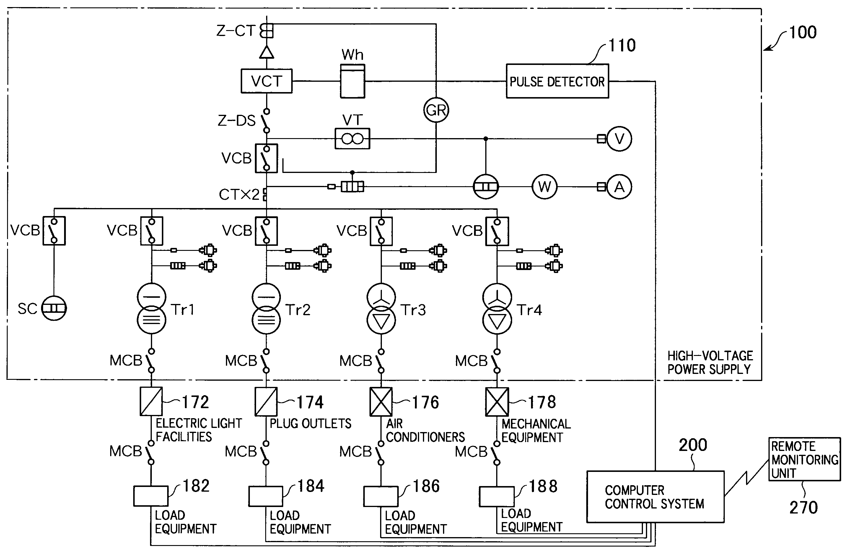
[0033]An energy management system of the present invention is a system which controls energy considerably by controlling each device within electrical facilities and mechanical facilities, so as to eliminate excess of air conditioners and related devices and then conducting year-round necessary and optimum operations of the respective facilities, which are established with maximum power consumption calculated at the time of construction design. In addition, amenities within the building constitute a system capable of conservation even if abnormal temperature, increase in occupancy load, and change in business category occur.

[0034]According to the energy management system of the present invention, conditions of operations and control of the respective equipment may be monitored in real time using a personal computer at a job site, a client's head office, a management company, ...


PUM


Abstract

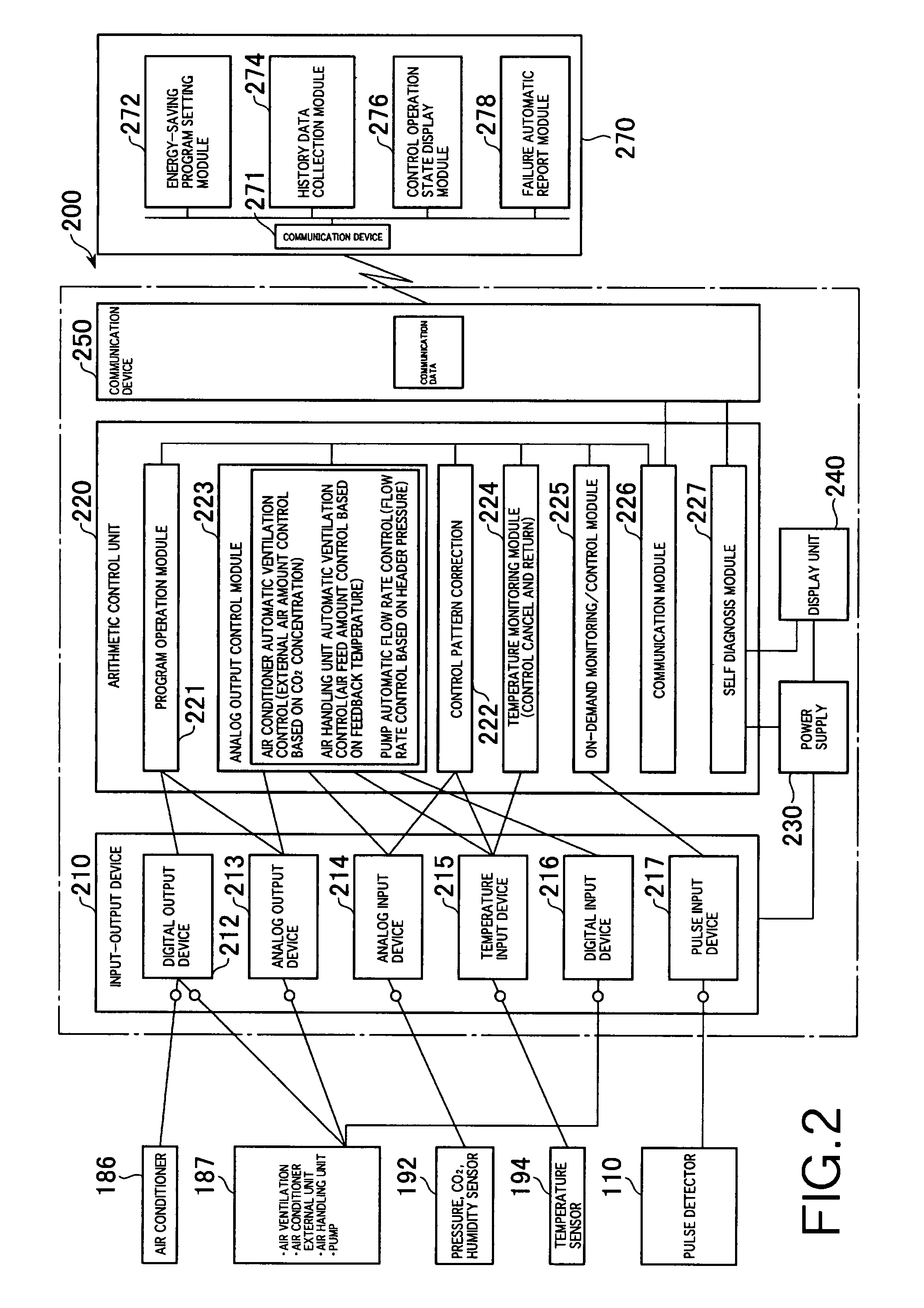
An energy management system for managing energy such as power consumed in a building in an optimal state to significantly save energy is provided. A computer control system (200) for controlling the energy management system performs program control as follows. Current date and time are acquired, a control pattern for that time is obtained using a control program, so as to determine whether operation of an air conditioner (186) is to be turned ON or OFF, and then output either an operation instruction or a stop instruction. A control signal is then output from a digital output unit (212) to the air conditioner (186). Thus, the air conditioner (186) temporarily stops operation according to a predetermined pattern for the program control. The current operating state is displayed on a display unit (240) and a remote monitoring unit (270).

Description

[0001]This is a 371 application of PCT / JP05 / 17884 filed on Sep. 28, 2005, the entire contents being incorporated by reference. The present application claims priority based on Japanese Patent Application No. 2005-032327, filed Feb. 8, 2005, the entirety of which being incorporated herein by reference.TECHNICAL FIELD[0002]The present invention relates to a computer-controlled energy management system for managing energy, such as electric power consumed in a building, in an optimal state while significantly saving energy.BACKGROUND ART[0003]Conventionally, a variety of systems for controlling power supplied to a building or the like have been proposed. However, according to these systems, when a power customer establishes a power reception / distribution facility and receives power supply therefrom, a supply contract is often made between the customer and a power company based on power supply terms and conditions, and controlling the contracted power under that contract. “Energy-saving ...

Claims


Application Information

Patent Timeline
Patent Type & Authority Patents(United States)
IPC IPC(8): G05D3/12G01R11/56G01R21/133F28F13/00F24F7/06F24F7/007F24F11/02F23N5/20G05D11/00G06F17/00
CPCG06Q50/06H02J3/14H02J13/0006Y02B70/3225Y02B70/3275H02J2003/143Y04S20/244Y02B70/3266Y04S20/242Y04S20/222H02J2310/14H02J13/00004H02J13/00034Y02B70/30H02J13/00002
Inventor MIWA
Owner KAZUO MIWA
Learn More