

System for measuring resonant frequency and delay time of quartz crystal microbalance
- Summary
- Abstract
- Description
- Claims
- Application Information
AI Technical Summary
Benefits of technology
Problems solved by technology
Method used
Image

Examples
Embodiment Construction
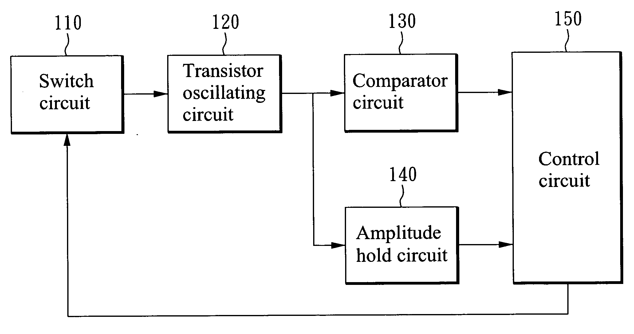
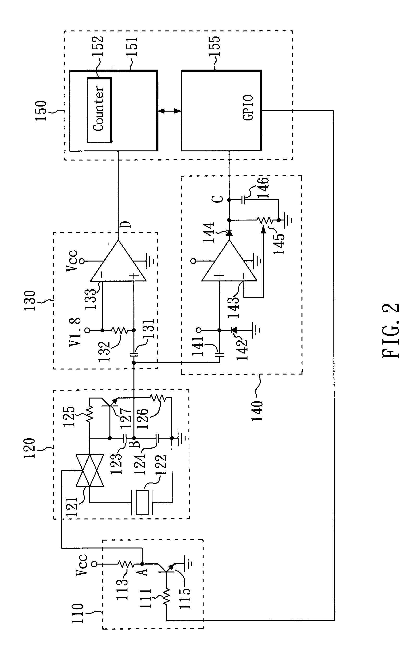
[0014]FIG. 1 is a block diagram of a system for measuring the resonant frequency and the delay time of the quartz crystal microbalance in accordance with the preferred embodiment of the present invention. This system comprises a switch circuit 110, a transistor oscillating circuit 120, a comparator circuit 130, an amplitude hold circuit 140, and a control circuit 150.
[0015]The transistor oscillating circuit 120 comprises a quartz oscillator 122 for generating an original oscillating signal. The switch circuit 110 is connected to the transistor oscillating circuit 120, while the switch circuit 110 receives a start signal, the transistor oscillating circuit 120 is enabled to generate the original oscillating signal.
[0016]The comparator circuit 130 is coupled to the transistor oscillating circuit 120 for converting the original oscillating signal to a square wave oscillating signal. The amplitude hold circuit 140 is coupled to the transistor oscillating circuit 120 and the control circ...
PUM
 Abstract
Description
Claims
Application Information