Performing blind scanning in a receiver

a receiver and blind scanning technology, applied in the field of blind scanning in the receiver, can solve the problems of excessive time, inefficient blind scanning functionality, and significant time required to perform analysis of the rf spectrum

Inactive Publication Date: 2010-03-23
SILICON LAB INC
View PDF11 Cites 20 Cited by
  • Summary
  • Abstract
  • Description
  • Claims
  • Application Information

AI Technical Summary

Benefits of technology

[0007]In one aspect, the present invention includes a method for receiving data corresponding to a portion of an incoming radio frequency (RF) spectrum, determining a set of estimates including one or more pairs of a channel frequency estimate and a symbol rate estimate from the data via a linear spectrum analysis, and determining a refined set of estimates from the set of estimates via at least one non-linear spectrum analysis. In this way, a blind scan process may be performed to obtain channel estimates in a rapid manner. The blind scan process may control various components of a receiver during the process. For example, a fine tuning filter bandwidth of the receiver may be set to correspond to the portion received, which may substantially correspond to a bandwidth maximum of the fine tuning filter.
[0009]Using a blind scan process in accordance with an embodiment of the present invention, a host controller of the receiver may obtain information useful in controlling the receiver, such as information regarding the presence of blockers and other adjacent channel information. Using this information, the host controller may more effectively control the receiver to improve performance.
[0011]In various implementations, a receiver may be tuned to receive a portion of an RF spectrum and generate digital data corresponding to the portion of the RF spectrum, calculate FFT bins from the digital data, determine if any of the FFT bins are above a predetermined threshold, and retune the receiver to a different portion of the RF spectrum if none of the FFT bins are above the threshold. Otherwise, a linear spectrum analysis may be performed on the bins above the threshold. In this way, a blind scan may be rapidly performed, as any scan steps lacking valid channels can be quickly bypassed.
[0012]Methods disclosed herein may further be used during frequency acquisition of a requested channel. In this way, frequency errors due to associated receiver components such as an antenna may be corrected. Thus, a blind scan controller can be used to analyze a portion of an RF spectrum around a desired channel to obtain a correct frequency for acquisition. Then the receiver can be tuned to the correct frequency based on the blind scan controller's analysis.

Problems solved by technology

However, existing blind scan functionality is relatively inefficient and requires significant time to perform analysis of an RF spectrum, such as a satellite spectrum.
This excessive time is incurred as typical blind scans exhaustively scan all possible combinations of frequency shifts and symbol rates to find every possible channel within a given frequency band and baud rate range.
However, because of the presence of adjacent channels, inter-modulation products confuse the analysis, as do the effects of filtering and aliasing.
Such frequency errors can lead to poor performance, or even the inability to properly tune a desired channel.

Method used


Image

  • Performing blind scanning in a receiver
  • Performing blind scanning in a receiver
  • Performing blind scanning in a receiver

Examples


Embodiment Construction

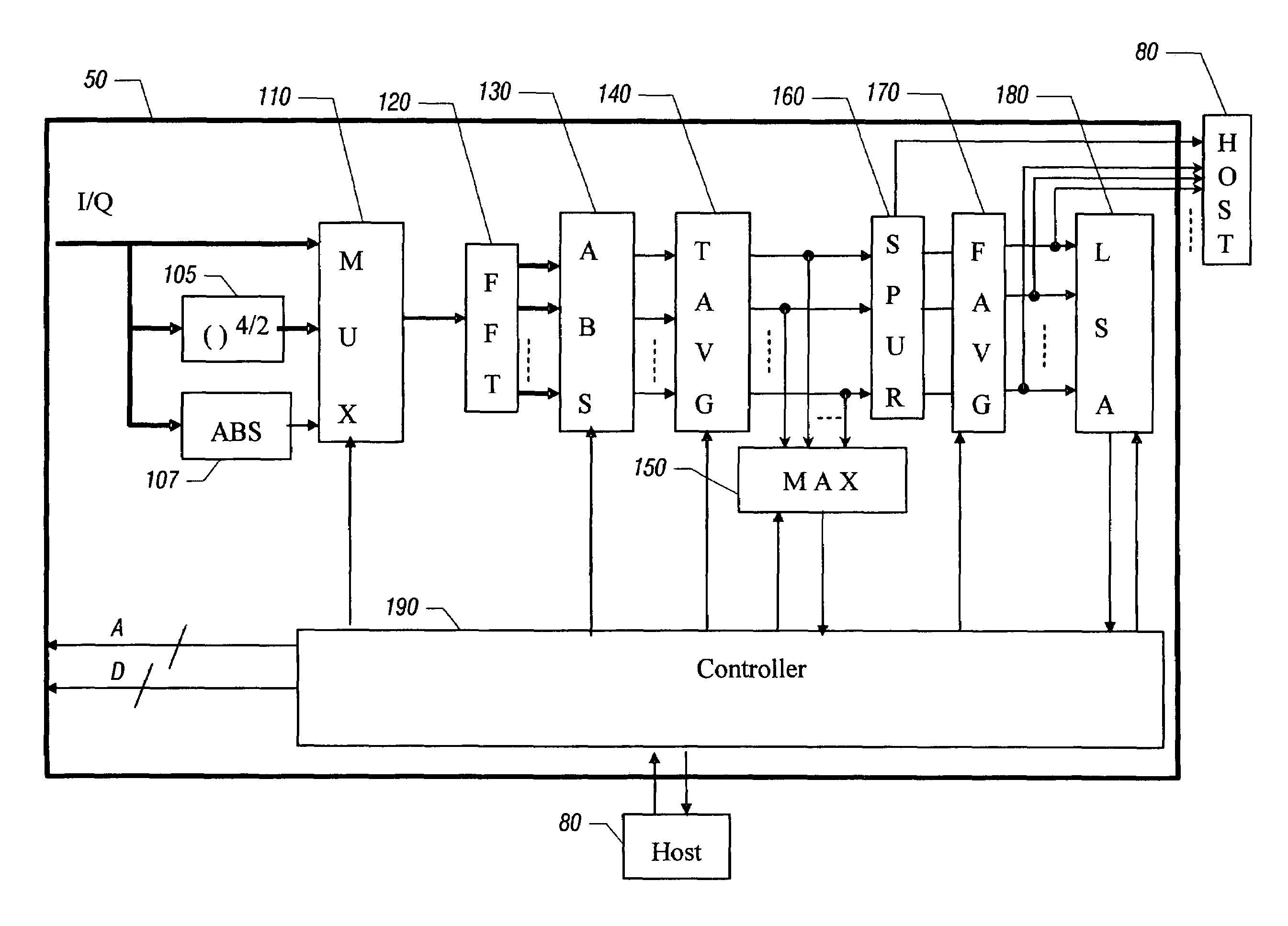
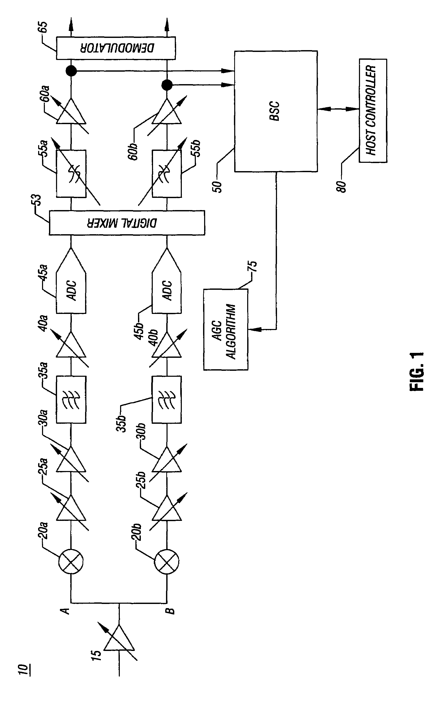
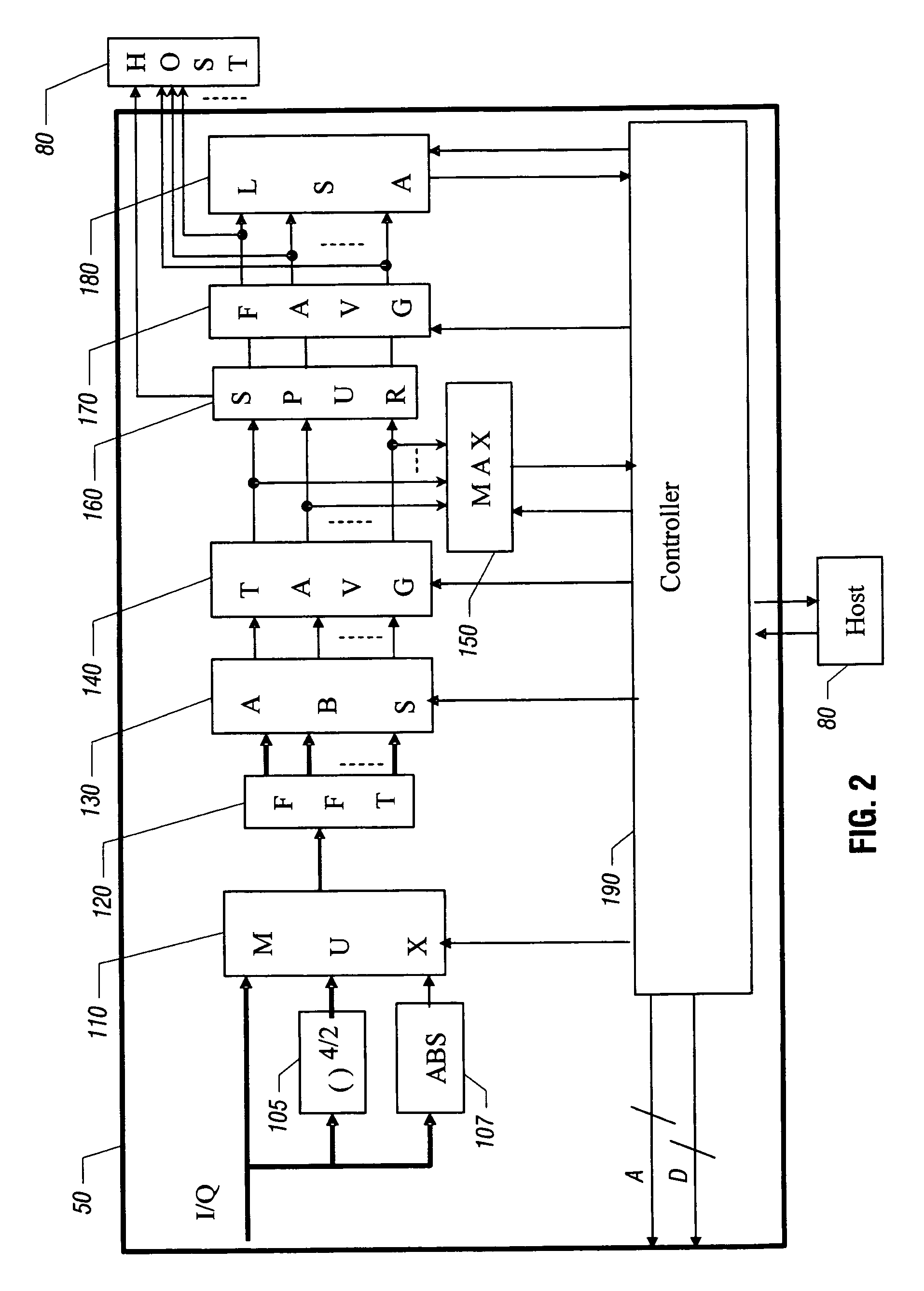
[0021]In various embodiments, blind scan processing may be performed using blind scan circuitry to identify channels present within a selected RF spectrum, as well as to determine the symbol rate of such channels, among other such information. In this manner, a list of carrier frequency estimates (CFEs) and corresponding symbol rate estimates (SREs) may be determined. More so, blind scan processing may be rapidly performed, as frequency ranges within an RF spectrum that do not include any valid channels can be quickly bypassed, avoiding the need for exhaustive scanning of the entire RF spectrum. Still further, similar blind scan circuitry may be used to perform frequency acquisition for a desired channel. In such manner, a selected channel can be tuned, even when an associated antenna such as an LNB is uncompensated for frequency errors.

[0022]In various implementations, a linear spectrum analysis (LSA) may be performed on incoming digital data to obtain raw estimates for CFE and SRE...


PUM


Abstract

In one embodiment, the present invention includes a method for receiving data corresponding to a portion of an incoming radio frequency (RF) spectrum, determining a set of estimates including one or more pairs of a channel frequency estimate and a symbol rate estimate from the data via a linear spectrum analysis, and determining a refined set of estimates from the set of estimates via at least one non-linear spectrum analysis.

Description

FIELD OF THE INVENTION[0001]The present invention relates generally to performing a blind scan in a receiver and more particularly to performing a blind scan in a satellite receiver.BACKGROUND[0002]Receivers are used in many applications to receive incoming radio frequency (RF) signals and convert them to baseband signals for desired processing. Various such receivers exist including cellular receivers, radio receivers, satellite receivers such as television satellite receivers, among many others.[0003]A receiver is typically coupled to receive incoming RF signals from an antenna and process the signals in various stages, including amplification stages, filtering stages, downconversion stages and the like. In a satellite system, such as a direct video broadcasting (DVB) system, an RF spectrum of a very wide band, e.g., approximately 1.3 gigahertz (GHz), includes many individual channels carrying programming. Typically, these channels are separated by some predetermined spacing, and ...

Claims


Application Information

Patent Timeline
Patent Type & Authority Patents(United States)
IPC IPC(8): H04B1/00
CPCH03J1/0091H04L27/2666H04N21/6131H04N21/4383H04N5/50
Inventor LI, JUNSONGZHOU, YAN
Owner SILICON LAB INC
Why Eureka
Try Eureka