Sinusoidal signal four parameters testing method and virtual apparatus signal detection device

A signal detection and sinusoidal signal technology, applied in the field of digital signal processing and analysis, can solve the problems of measurement accuracy and clock frequency limitation, cannot meet the accuracy requirements of the industrial field, and does not have the ability to save waveform data and measurement result data, etc.

Inactive Publication Date: 2008-08-27
BEIHANG UNIV
View PDF5 Cites 28 Cited by
  • Summary
  • Abstract
  • Description
  • Claims
  • Application Information

AI Technical Summary

Problems solved by technology

But it has the following disadvantages: First, due to the adoption of the zero-crossing detection method, the measurement error is large and the anti-interference ability is poor when the signal has zero drift and is interfered by random noise.
Second, since the measurement result is obtained by counting pulses, the measurement accuracy is limited by the accuracy and frequency of the clock
Third, since all are implemented by hardware, it is inevitable to introduce new interference in the measurement process
Third, neither of them gives the detection method of the DC component in the sinusoidal signal
[0013] 2. The main problems of traditional signal detection devices
Therefore, the measurement accuracy is low and cannot meet the increasingly high accuracy requirements in the industrial field
[0016] (2) The hardware cost of traditional testing instruments is high, especially the cost of multi-channel measuring instruments is very high
[0017] (3) Traditional detection instruments cannot realize automatic detection, do not have the function of saving waveform data and measurement result data, and cannot measure all parameters of sinusoidal signals at the same time
[0018] (4) The performance of traditional measuring instruments mainly depends on the performance of hardware, so the adaptability to signals is poor

Method used


Image

  • Sinusoidal signal four parameters testing method and virtual apparatus signal detection device
  • Sinusoidal signal four parameters testing method and virtual apparatus signal detection device
  • Sinusoidal signal four parameters testing method and virtual apparatus signal detection device

Examples


Embodiment Construction

[0110] The present invention will be further described below in conjunction with the accompanying drawings and embodiments.

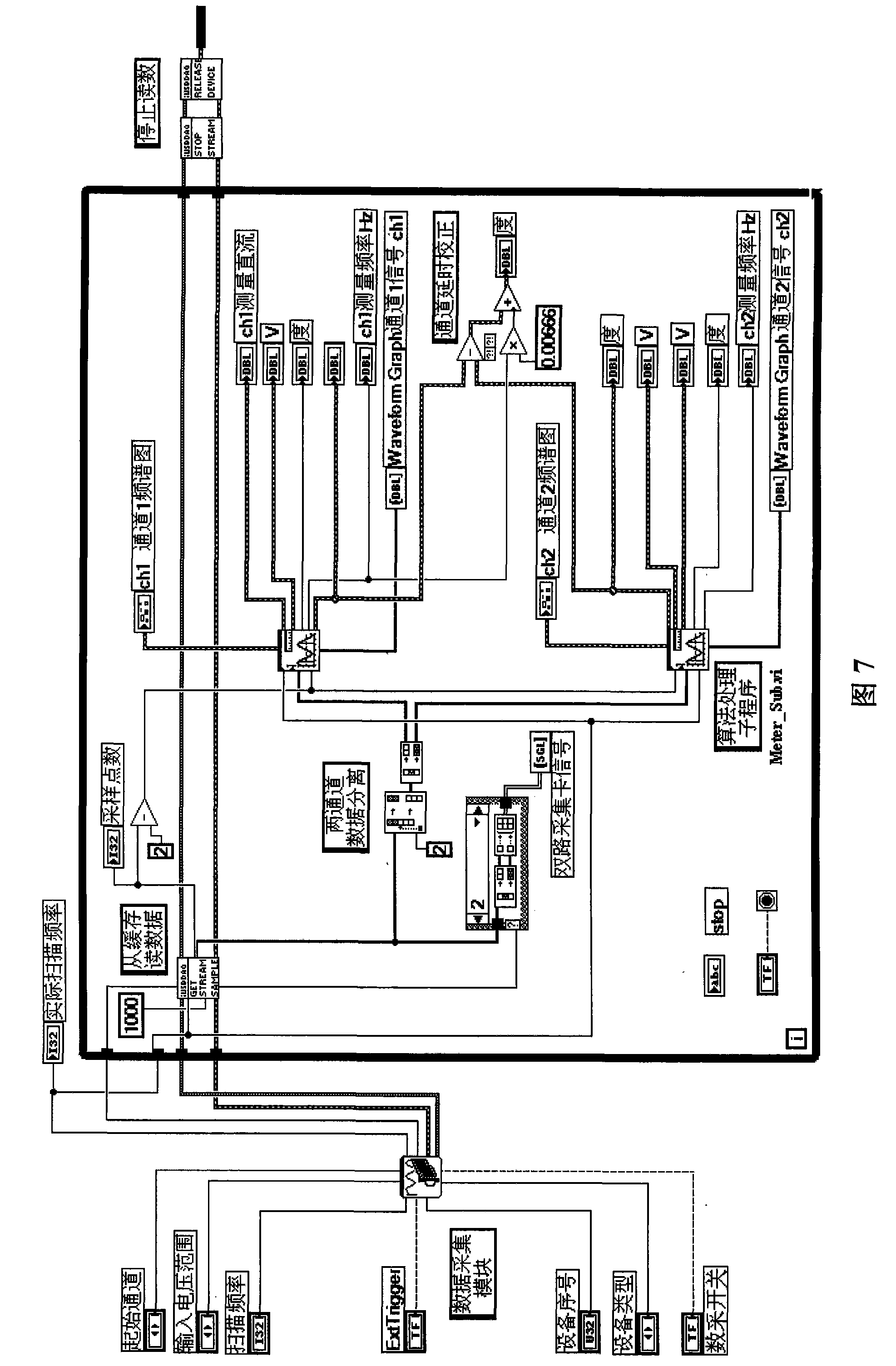
[0111] The signal detection algorithm step that the present invention proposes is as follows:

[0112] Step 1: Continuously sample the signal to be tested to obtain a 2N-1 digital sequence L (numbered 0, 1, ..., 2N-2);

[0113] Step 2: Form the 0~N-1 points of L into a new sequence L1, and form the N-1~2N-2 points of L into a new sequence L2;

[0114] Step 3: Carry out fast Fourier transform (FFT) to sequence L1, L2 respectively, obtain the frequency spectrum of two sequences respectively;

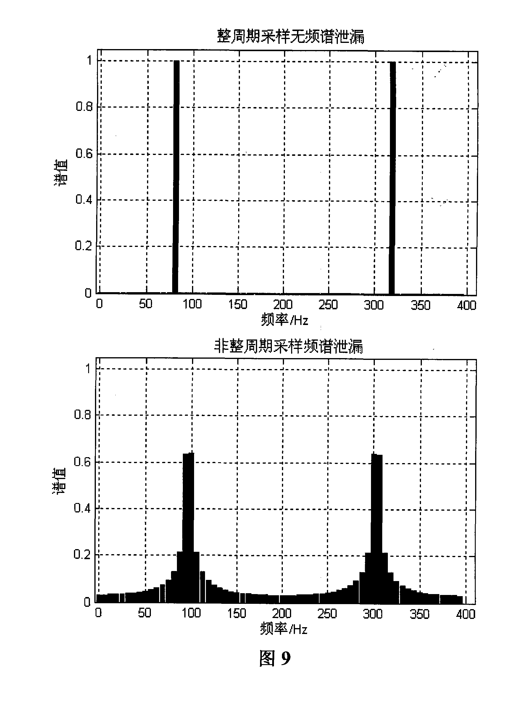
[0115] Step 4: Extract the amplitude and phase angle information of the spectral peak of the two sequences of AC components in the spectrum, and obtain the preliminary measurement values ​​of frequency and phase after preliminary processing to eliminate the spectrum leakage error;

[0116] Step 5: Measure the amplitude, frequency and phase (difference) of the high...


PUM


Abstract

The present invention relates to a sine signal four parameters detection method and a virtual instrument signal detection device. The device consists of a signal modulating unit, a data acquisition unit, a microcomputer and a signal processing unit. The signal generated by a sensor and a signal source is modulated. An analog sine signal is sampled and quantized into a digital signal by a data acquisition card. The digital signal is sent to a computer via a data interface. With the signal detection method of the present invention, FFT conversion is carried out for two continuously sampled signal series respectively. The spectrum peak values of the direct current amount and the alternating current amount of the signal are respectively extracted with the application of the frequency-selecting property of the FFT. With precise phase correction and frequency correction, the amplitude, the frequency, the phase (difference) and the direct current component parameter of the sine signal are accurately measured. Afterwards, the signal wave pattern, the spectrogram and the measuring result are outputted via a display. The dynamic measuring result is preserved to be a data document.

Description

1. Technical field [0001] The invention relates to a four-parameter detection method of a sinusoidal signal and a virtual instrument signal detection device, in particular to a method for measuring the amplitude, frequency, phase (difference) and DC component of a sinusoidal signal with high precision, and a virtual instrument signal A detection device belongs to the field of digital signal processing and analysis. 2. Background technology [0002] In industrial fields such as sensor signal detection and analysis, electrical measurement and power system monitoring, it is often necessary to perform high-precision measurement of various parameters of sinusoidal signals. [0003] Sine signal measurement methods are generally divided into analog measurement and digital measurement. The traditional analog measurement method is mainly realized by hardware circuit, and its measurement accuracy mainly depends on the performance of the measurement circuit. Digital measurement, also...

Claims


Application Information

Patent Timeline
Patent Type & Authority Applications(China)
IPC IPC(8): G01R23/16G01R15/12
Inventor 付连锐王兆仲张军香陈伟
Owner BEIHANG UNIV
Why Eureka
Try Eureka