Plasma display panel and plasma display device including the plasma display panel
- Summary
- Abstract
- Description
- Claims
- Application Information
AI Technical Summary
Benefits of technology
Problems solved by technology
Method used
Image

Examples
first embodiment
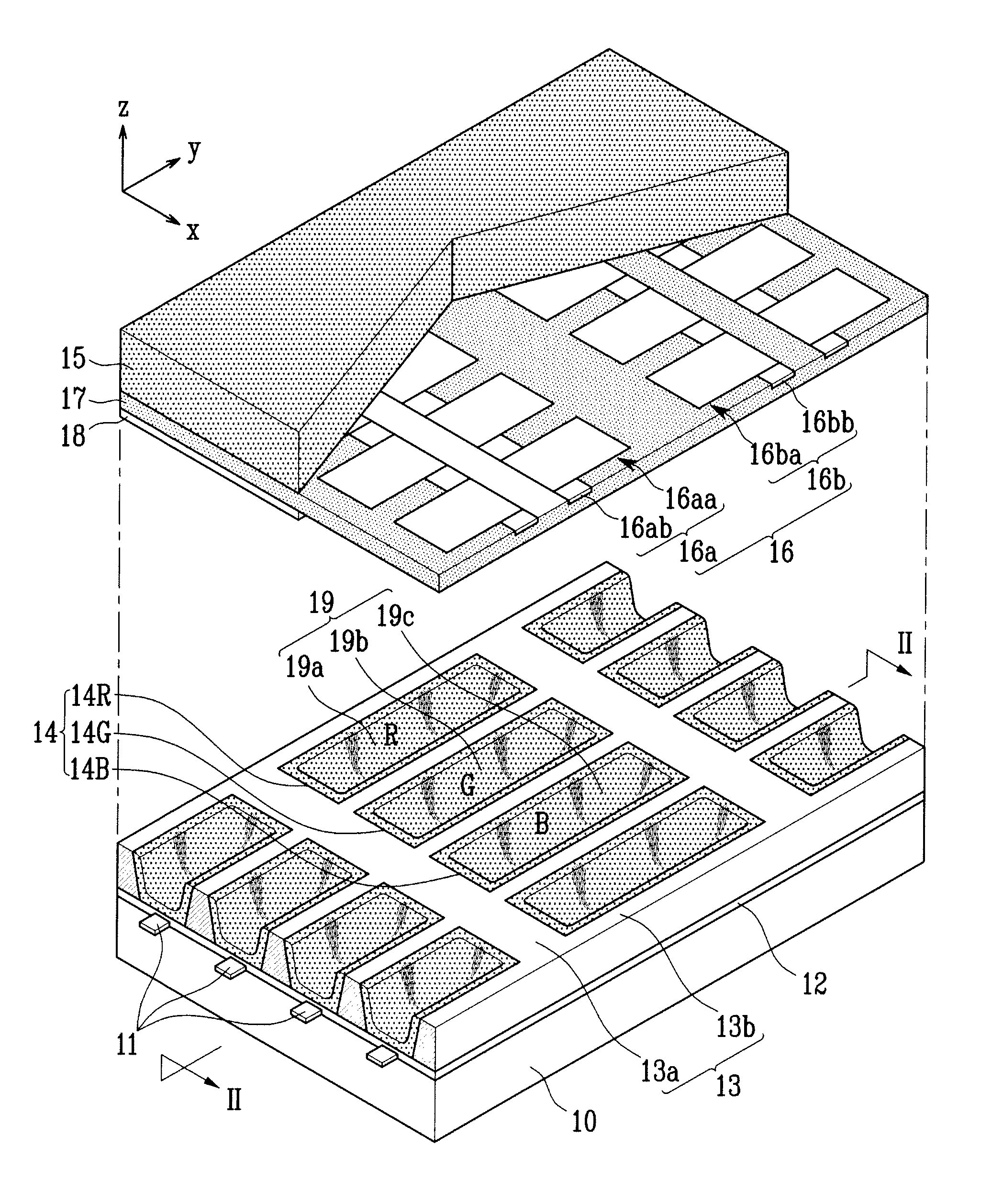
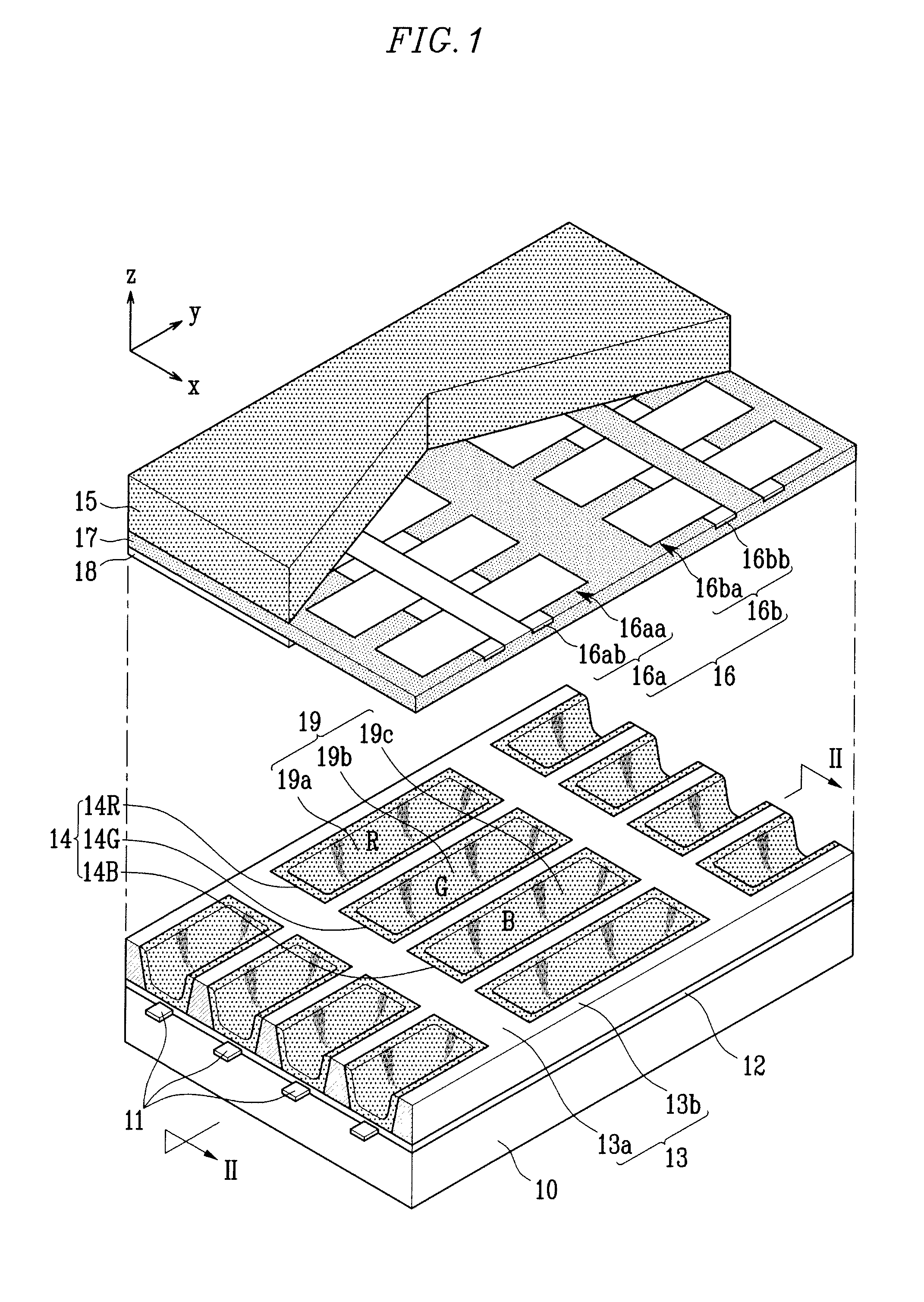
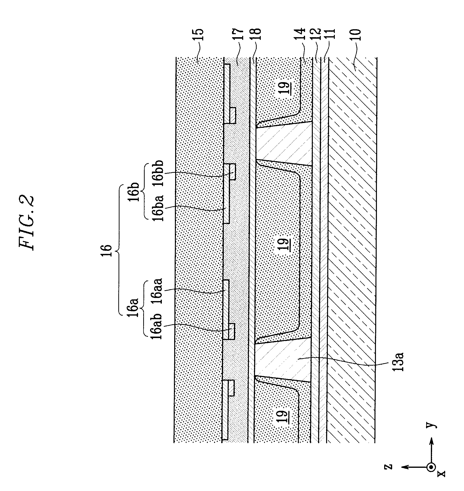
[0029]FIG. 1 is a partially exploded perspective view illustrating a plasma display panel according to the present invention. FIG. 2 is a cross sectional view taken along the line II-II of FIG. 1.
[0030]Referring to FIGS. 1 and 2, the plasma display panel according to the first embodiment of present invention includes rear and front substrates 10 and 15, discharge cells 19 which are defined by barrier ribs 13 between the rear and front substrates 10 and 15, and address and display electrodes 11 and 16 which are formed corresponding to the discharge cells 19.
[0031]The rear substrate 10 faces the front substrate 15, and the rear and front substrates 10 and 15 are parallel with each other at a distance (e.g., a predetermined gap between the substrates). The address electrodes 11 extend in a first direction (i.e., a y-axis direction of FIG. 1) on an upper surface of the rear substrate 10. In addition, the address electrodes 11 are parallel with one another, and are spaced apart from one ...
second embodiment
[0065]As shown in FIG. 6, the plasma display panel in the second embodiment includes an image display region 40′ on which images are displayed. In FIG. 6, only a part of the image display region 40′ is shown. The image display region 40′ includes a first region 40a′ where the phosphor layers 14 are visible through the front substrate 15 and the front dielectric layer 17 and a second region 40b′ where the barrier ribs 13′ are visible through the front substrate 15 and the front dielectric layer 17.
[0066]As shown in FIG. 6, when the first color of the front substrate 15 is blue, and the third color of the front dielectric layer 17 is yellow red, a part where the front substrate 15 overlaps the front dielectric layer 17 appears black or substantially black.
[0067]In addition, when the third color of the front dielectric layer 17 is yellow red, and the second color of the phosphor layers 14 is blue, a part where the front dielectric layer 17 overlaps the phosphor layers 14 appears black ...
PUM
 Abstract
Description
Claims
Application Information
 - R&D
- Intellectual Property
- Life Sciences
- Materials
- Tech Scout
- Unparalleled Data Quality
- Higher Quality Content
- 60% Fewer Hallucinations
Browse by: Latest US Patents, China's latest patents, Technical Efficacy Thesaurus, Application Domain, Technology Topic, Popular Technical Reports.
© 2025 PatSnap. All rights reserved.Legal|Privacy policy|Modern Slavery Act Transparency Statement|Sitemap|About US| Contact US: help@patsnap.com