Switching hub and LAN system

a technology of switching hub and lan, which is applied in the direction of data switching network, data switching by path configuration, digital transmission, etc., can solve the problems of increasing cost and complicated configuration and setting, and achieve the effect of not making the configuration of network devices complicated

Inactive Publication Date: 2008-08-07
HITACHI METALS LTD
View PDF7 Cites 115 Cited by
  • Summary
  • Abstract
  • Description
  • Claims
  • Application Information

AI Technical Summary

Benefits of technology

[0034]Accordingly, it is an object of this invention to provide a switching hub and a LAN system using the switching hub, capable of flexibly adapting to frame relay settings without making the configuration of network devices complicated even in an environment where a plurality of VLANs are provided.

Problems solved by technology

However, this setting has the problem of relaying to the prohibited relay 6 port although relay 1 is permitted to be performed.
In order to prevent this, when building plural VLANs, setting the plural VLANs for the ports to perform router routing between the VLANs is considered, but there is the problem that when building plural independent VLANs, a router which is adaptable for this is required, which makes configuration and setting complicated, leading to an increase in cost.

Method used


Image

  • Switching hub and LAN system
  • Switching hub and LAN system
  • Switching hub and LAN system

Examples


Embodiment Construction

[0051]Switching Hub Configuration

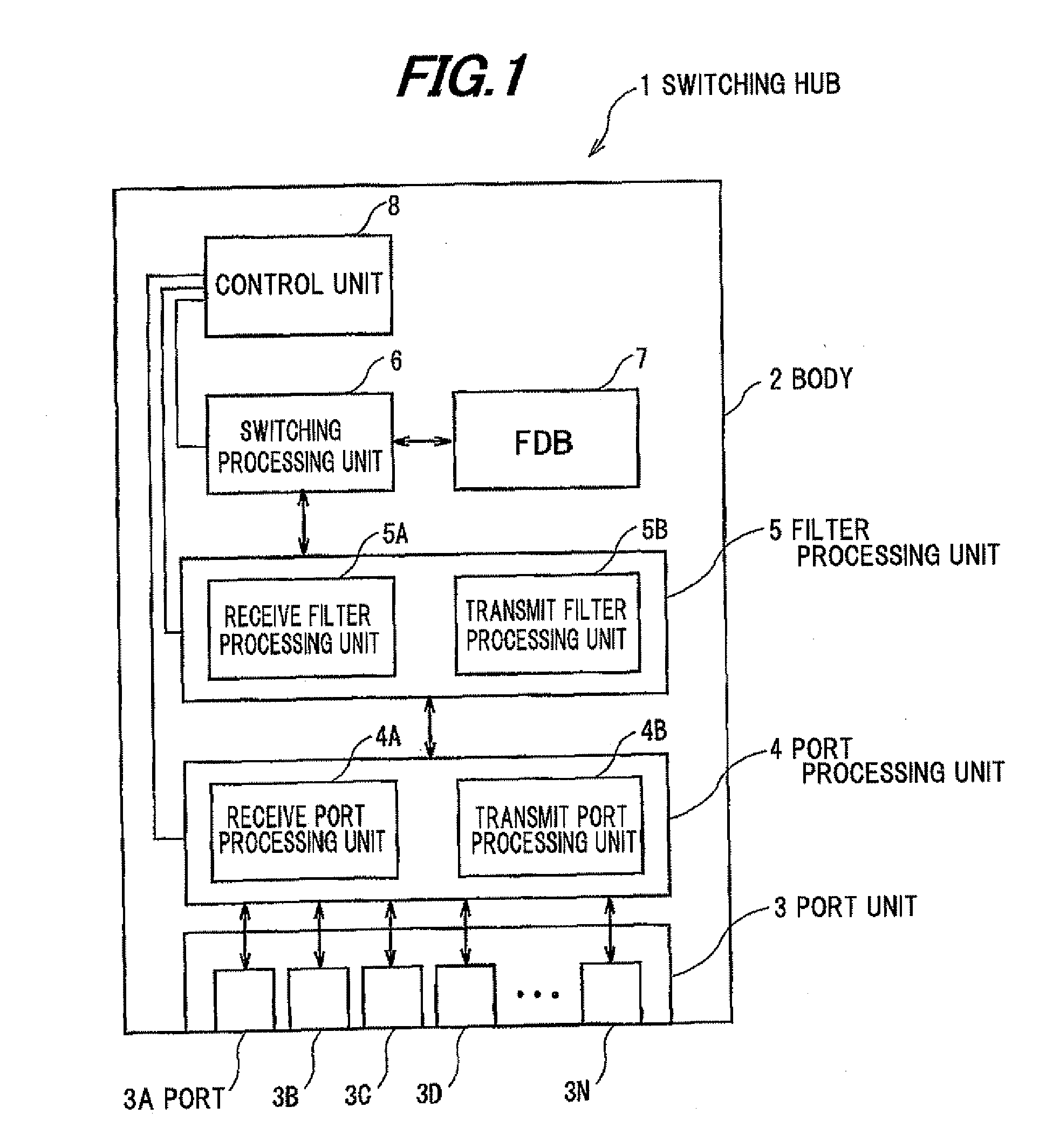
[0052]FIG. 1 is a schematic configurational diagram showing a switching hub in this embodiment. This switching hub 1 includes a port unit 3 comprising plural ports 3A-3N provided for connecting communication cables, such as LAN cables, etc., to a side of a body 2, a port processing unit 4 comprising a receive port processing unit 4A and a transmit port processing unit 4B, a filter processing unit 5 comprising a receive filter processing unit 5A and a transmit filter processing unit 5B, a switching processing unit 6 for determining a frame-relaying VLAN, a FDB (Forwarding Data Base) 7 with frame destination addresses registered therein, and a control unit 8 for setting VLAN-IDs corresponding to the plural ports 3A-3N respectively of the port unit 3.

[0053]The port unit 3 comprises the plural ports 3A-3N to which LAN communication cables are connectable.

[0054]The port processing unit 4 is for adding and deleting a VLAN tag to and from a frame relayed to...


PUM


Abstract

A switching hub is provided with a control unit for setting, for a port, a VLAN-ID comprising a subgroup ID of a subgroup constituting a VLAN, and a sub-ID of a group contained in the subgroup ID, and a switching processing unit for relaying a frame, which contains the VLAN-ID, via the port, which matches the VLAN-ID

Description

[0001]The present application is based on Japanese patent application No. 2007-028511 filed on Feb. 7, 2007, the entire contents of which are incorporated herein by reference.BACKGROUND OF THE INVENTION[0002]1. Field of the Invention[0003]This invention relates to a switching hub and a LAN system.[0004]2. Description of the Related Art[0005]With the widespread use of personal computers and the Internet, many companies have an Ethernet (registered trademark) local area network (LAN) built and utilized for various businesses. In large companies, because of their large-scale local area network, virtual LAN (herein referred to as VLAN) technology is widely utilized that allows the network to be grouped for each post or project.[0006]The VLAN is a technology for virtually grouping computers on a LAN regardless of physical cable wiring or computer installation places, and is standardized by IEEE (Institute of Electrical and Electronic Engineers) 802.1Q, and many switching hubs equipped wi...

Claims


Application Information

Patent Timeline
Patent Type & Authority Applications(United States)
IPC IPC(8): H04L12/28H04L12/44H04L12/46
CPCH04L2012/445H04L12/4641H04L12/46H04L9/40
Inventor SETO, KOICHIROSEKIGUCHI, AKIHIRO
Owner HITACHI METALS LTD
Why Eureka
Try Eureka