Image forming apparatus and method for controlling feeding of sheets

a technology of image forming apparatus and paper output device, which is applied in the field of image forming apparatus and paperoutput device, can solve the problems of inability to take into account the type of paper, the processing performed by the paper-output device may not be synchronized with the processing performed by and the operation of the image forming apparatus is limited, so as to reduce the waiting time, improve processing efficiency, and shorten the waiting time in image formation

Inactive Publication Date: 2008-08-07
CANON KK
View PDF8 Cites 18 Cited by
  • Summary
  • Abstract
  • Description
  • Claims
  • Application Information

AI Technical Summary

Benefits of technology

[0007]The present invention provides an image forming apparatus that synchronizes the processing performed by the image forming apparatus and the processing performed by the paper-output device by taking the sheet type into account. This reduces waiting time during image formation and improves processing efficiency. More specifically, information about sheet type is included in the paper-output reservation for the paper-output device. The paper-output device calculates the time when it is possible to receive a subsequent sheet. The calculation result is reflected in determining the timing to start forming an image in the image forming apparatus. The processing performed by the paper-output device and the processing performed by the image forming apparatus are thus synchronized, whereby an apparatus requiring a short waiting time in image formation and having a high processing efficiency can be provided.

Problems solved by technology

However, in the structure of Japanese Patent Laid-Open No. 11-292390, information about the sheet type is not taken into account when the image forming apparatus schedules the processing of the sheets.
Therefore, depending on the sheet type or the sheet conveyance speed of the image forming apparatus, the processing performed by the paper-output device may not be synchronized with the processing performed by the image forming apparatus.
Thus, the operation of the image forming apparatus is limited.

Method used


Image

  • Image forming apparatus and method for controlling feeding of sheets
  • Image forming apparatus and method for controlling feeding of sheets
  • Image forming apparatus and method for controlling feeding of sheets

Examples


first embodiment

Overall Structure

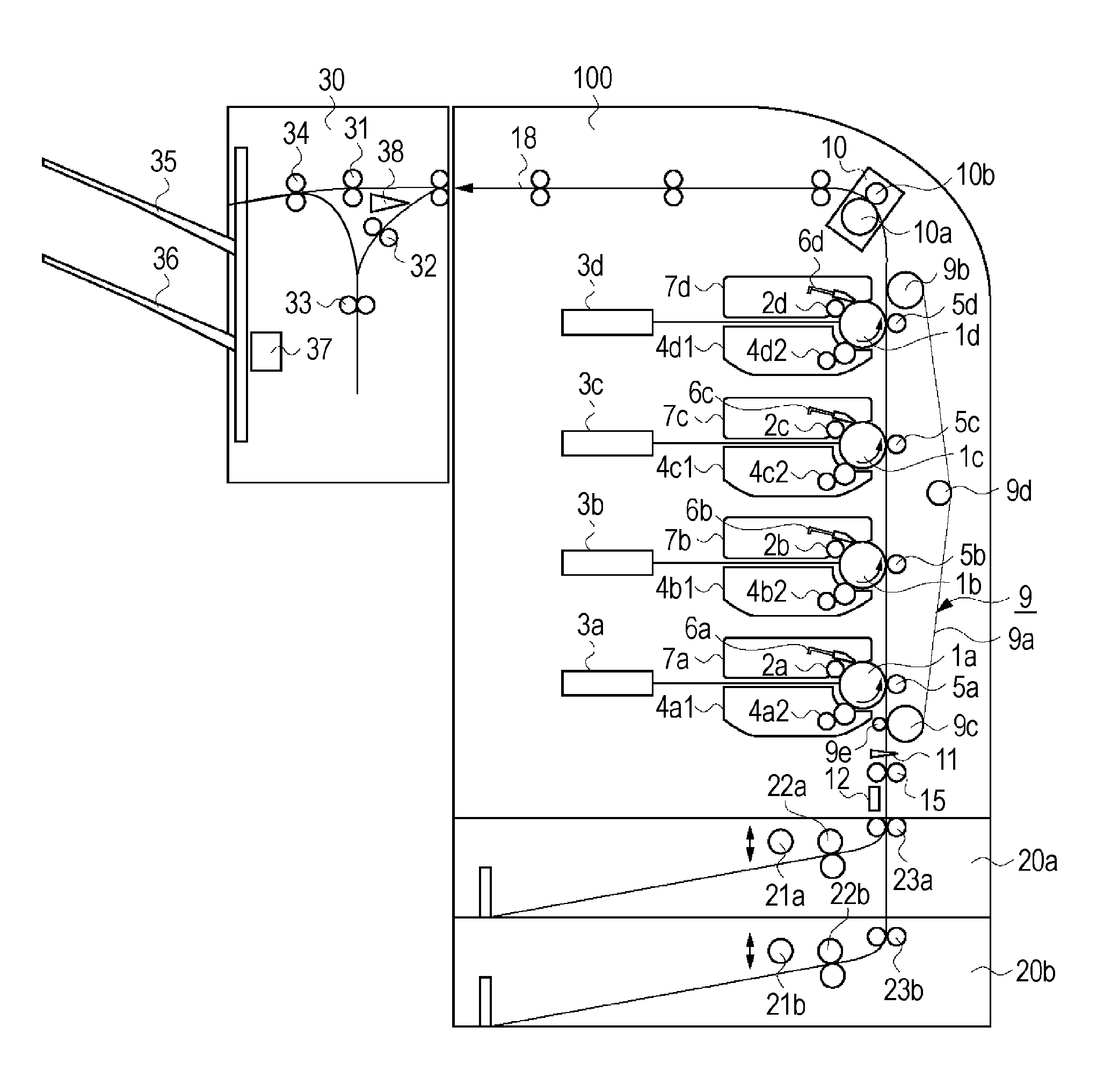
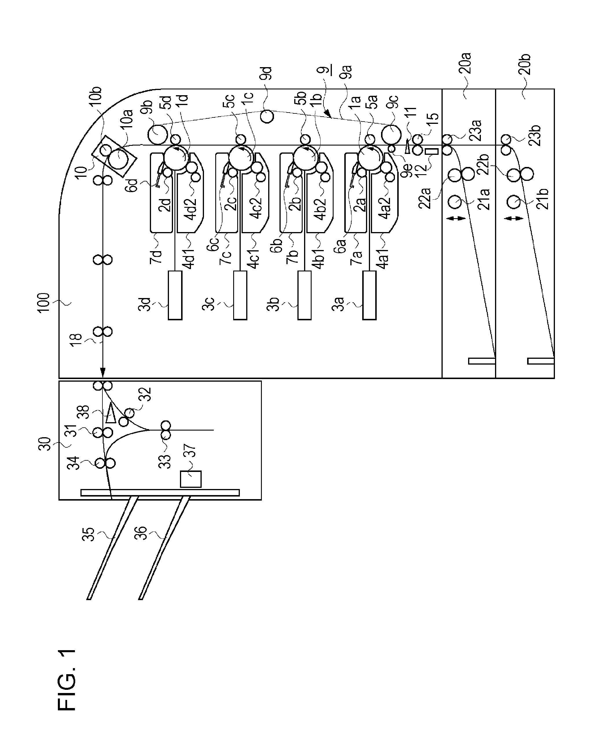
[0023]FIG. 1 shows the overall structure of a laser printer serving as an image forming apparatus. An image forming apparatus 100 includes photosensitive drums 1a, 1b, 1c, and 1d (generally denoted by reference numeral 1), which serve as image bearing members. Charging portion 2a, 2b, 2c, and 2d (generally denoted by reference numeral 2) are provided adjacent the photosensitive drums 1a, 1b, 1c, and 1d, respectively, and uniformly charge the surfaces thereof with the rotation. In addition, the image forming apparatus 100 includes exposure members 3a, 3b, 3c, and 3d (generally denoted by reference numeral 3) for emitting laser beams according to image data and forming electrostatic latent images on the photosensitive drums 1a, 1b, 1c, and 1d, and development members 4a, 4b, 4c, and 4d (generally denoted by reference numeral 4) for depositing toner on the electrostatic latent images form toner images. Further, the image forming apparatus 100 includes transfer members ...

second embodiment

[0089]In the first embodiment, a configuration in which the controller 201 acquires the information about sheet type from the engine control unit 203 prior to making a print reservation is described.

[0090]In the present embodiment, a configuration will be described in which the controller 201, when making a print reservation to the engine control unit 203, acquires the information about sheet type preset to a paper-feed port to be specified in a print reservation from the engine control unit 203 as a return status. The information acquired as a return status of the print reservation is the information about sheet type preset to the respective paper-feed ports. Examples of information about sheet type include, for example, the sheet size (such as A4 or B5), the sheet type (such as glossy paper, normal paper, rough paper, cardboard, thin paper, or OHP sheet). Not only the aforementioned information, but also information such as the sheet conveyance speed may be included in the paper-o...

third embodiment

[0118]In the above-described first and second embodiment, the controller 201 adds the information about sheet type acquired from the engine control unit 203 to a paper-output reservation to the external-paper-output-device control unit 202. The external-paper-output-device control unit 202 calculates a subsequent-sheet receiving time on the basis of the information about sheet type, and the controller 201 acquires the subsequent-sheet receiving time calculated by the external-paper-output-device control unit 202.

[0119]In the present embodiment, a configuration is described in which, if a sheet type specified in a paper-output reservation does not match a sheet type detected in performing printing, the subsequent-sheet receiving time is renewed on the basis of the information about sheet type detected at the latest. In the present embodiment, a print delay time is calculated on the basis of the renewed subsequent-sheet receiving time.

[0120]FIG. 8 shows an operation flow of the contro...


PUM


Abstract

An image forming apparatus, to which a paper-output device for processing a sheet after image formation is attached, includes a paper-feed unit for feeding a sheet for image formation; a detection unit for detecting a type of the sheet fed from the paper-feed unit; an image forming section for forming an image on the sheet fed from the paper-feed unit; and a control unit for determining a sheet-feed timing based on a sheet-processing time used by the paper-output device corresponding to a preset sheet type. If the preset sheet type matches the sheet type detected by the detection unit, the control unit determines the sheet-feed timing based on the sheet-processing time corresponding to the preset sheet type. If not, the control unit determines the sheet-feed timing based on the sheet-processing time corresponding to the sheet type detected by the detection unit.

Description

BACKGROUND OF THE INVENTION[0001]1. Field of the Invention[0002]The present invention relates to an image forming apparatus and a paper-output device to be attached to the image forming apparatus. More specifically, the present invention relates to processing of recording paper (sheets) performed by the image forming apparatus and the paper-output device.[0003]2. Description of the Related Art[0004]An image forming apparatus, to which an optional paper-output device for processing and outputting recording paper (a sheet) after image formation is attached, is known. In such an image forming apparatus, when forming an image on a sheet, the image forming apparatus requests the paper-output device to perform paper-output processing under certain paper-output conditions that specifies a paper-output bin and necessity of stapling. The paper-output device processes and outputs a sheet in accordance with the request of the paper-output processing from the image forming apparatus. This struc...

Claims


Application Information

Patent Timeline
Patent Type & Authority Applications(United States)
IPC IPC(8): G03G21/14G03G15/00
CPCG03G2215/0145G03G15/6573
Inventor YOSHIZAWA, RYUICHI
Owner CANON KK
Why Eureka
Try Eureka