Hole saw with depth stop

Inactive Publication Date: 2008-08-07
GREENLEE TEXTRON
View PDF14 Cites 37 Cited by
  • Summary
  • Abstract
  • Description
  • Claims
  • Application Information

AI Technical Summary

Benefits of technology

[0009]Briefly, the present invention discloses a hole saw which includes a blade and a depth stop. A plurality of slots are provided through the blade and the depth stop is removably mounted in one of the plurality of slots. The blade with the mounted depth stop is then rotated by an associated drill to form a hole in the workpiece. As the blade penetrates the workpiece, t

Problems solved by technology

This presents the danger that some of the wires already present will be cut or otherwise damaged during the hole cutting operation as the hole saw penetrates the panel.
The cut or damaged wires present an electrical hazard once the wires are energized.
This hole saw has disadvantages including that the stop requires four screws for attaching it to the hole saw, that the components are larger and more expensive than necessary, and that

Method used


Image

  • Hole saw with depth stop
  • Hole saw with depth stop
  • Hole saw with depth stop

Examples


first embodiment

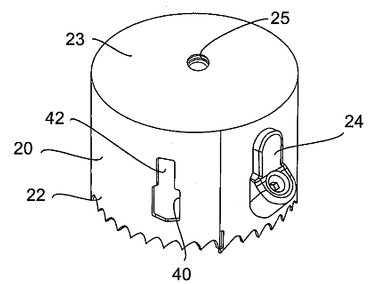
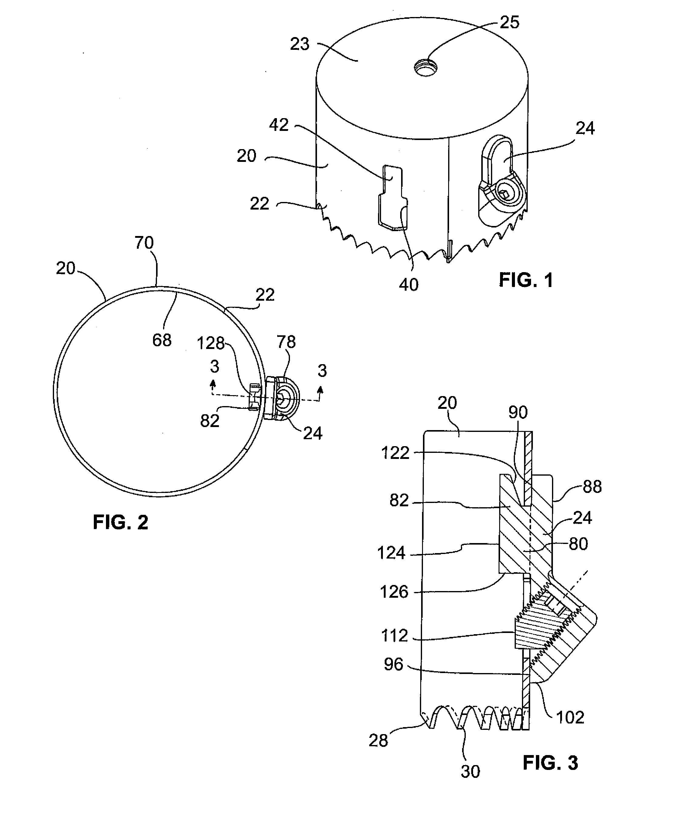
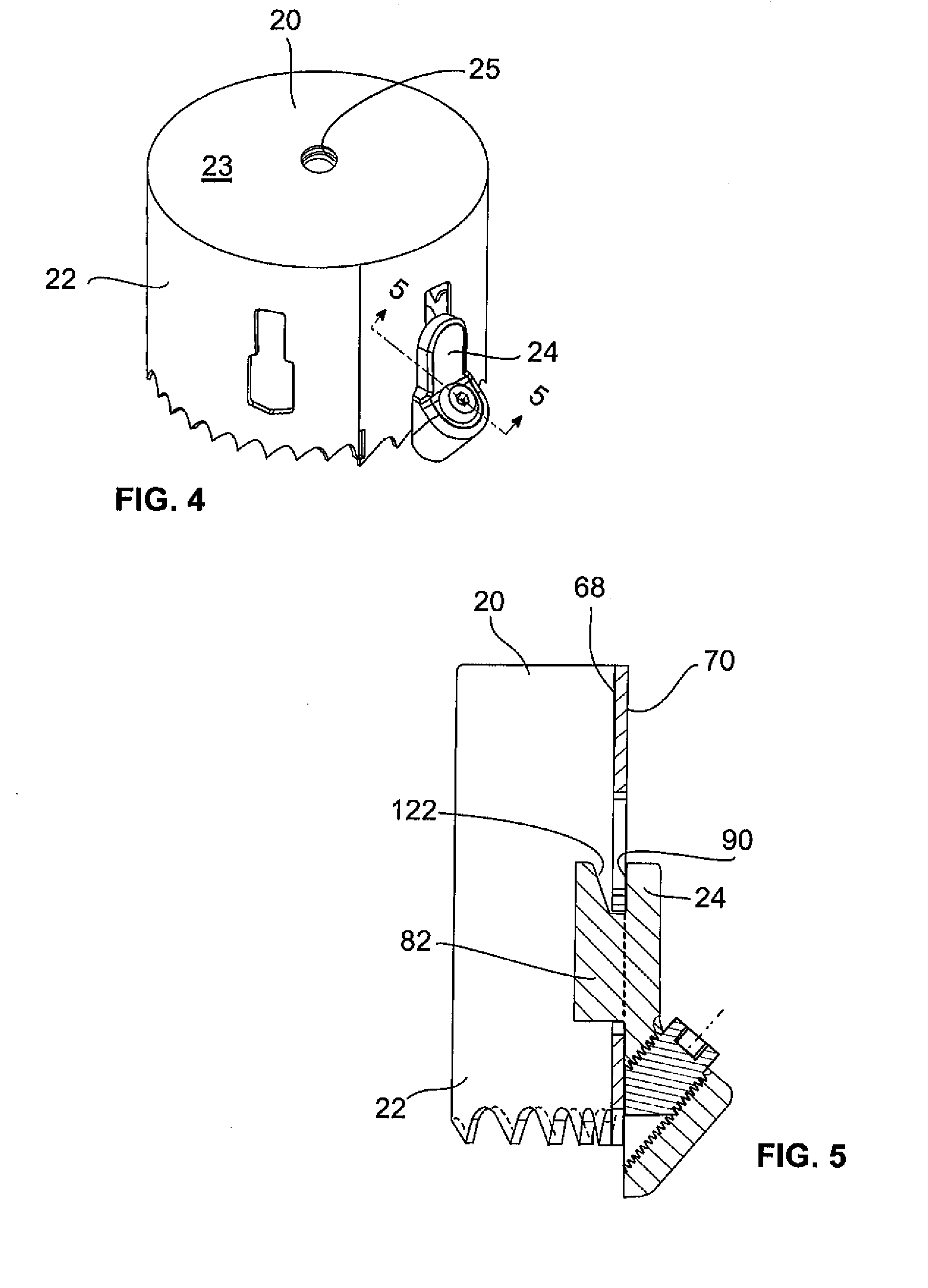
[0033]The depth stop 24 is mounted to the blade 22. the depth stop 24 is shown in FIGS. 7-9. The depth stop 24 has a distal end 74 and a proximal end 76. The depth stop 24 includes a main body 78, a abutment portion 80 (see FIG. 9) extending from the main body 78 and a retention ear 82 extending from the abutment portion 80. The main body 78, the abutment portion 80 and the retention ear 82 are integrally formed.

[0034]The main body 78 includes a generally planar portion 84 and an enlarged end portion 86. The planar portion 84 includes an outer surface 88, an alignment surface 90 opposite the outer surface 88, and a peripheral edge 92 extending between the outer surface 88 and the alignment surface 90. The peripheral edge 92 is generally rounded at the proximal end 76 of the depth stop 24.

[0035]The enlarged end portion 86 extends from the planar portion 84 and is formed from a generally tubularly-shaped wall 94 generally having an interior surface 98, an exterior surface 97, and an a...

second embodiment

[0038]the depth stop 24a is shown in FIGS. 10-15. The depth stop 24a is similar to the depth stop 24 shown in FIGS. 7-9 with the following exceptions. Elements of depth stop 24a which are similar to elements of depth stop 24 are not described again herein and have been identified with the same reference numerals.

[0039]Unlike the peripheral edge 92 of the depth stop 24 which is rounded, the peripheral edge 292 of the planar portion 84 of the depth stop 24a is faceted at the proximal end.

[0040]The enlarged end portion 86 of depth stop 24a includes a wall 294 which defines the locking member passageway 104. Unlike the exterior surface of the wall 94 of depth stop 24 which is generally smooth and rounded, the exterior surface of the wall 294 of the depth stop 24a is faceted and includes a plurality of planar surfaces 300a, 300b, 300c, 300d, 300e. Each surface 300a, 300b, 300c, 300d, 300e generally extends parallel to the central axis 110 of the locking member passageway 104. The depth s...


PUM

PropertyMeasurementUnit
Angleaaaaaaaaaa
Angleaaaaaaaaaa
Widthaaaaaaaaaa

Abstract

A hole saw includes a depth stop for limiting the depth of penetration of the hole saw into a workpiece. The blade of the hole saw includes a plurality of slots, one of which is used to receive the depth stop. The depth stop is mounted to the blade by positioning a portion of the depth stop within the slot and sliding the depth stop from an unsecured position to a secured position. Once in the secured position, a locking member is moved within the depth stop to secure the depth stop in place. In use, the blade is advanced through the workpiece until the depth stop contacts the proximal surface of the workpiece.

Description

[0001]This application claims the domestic benefit of U.S. Provisional Application Ser. No. 60 / 897,317 filed on Jan. 25, 2007, which disclosure is hereby incorporated by reference.FIELD OF THE INVENTION[0002]This invention is generally directed to a hole saw with a depth stop.BACKGROUND OF THE INVENTION[0003]Hole saws have been used by tradesman for drilling holes in paneling and the like for a number of years. In particular, electricians routinely use hole saws made from a tubularly-shaped saw blade to drill holes into electrical boxes made out of sheet metal to allow the ingress and egress of wires. After the hole is drilled, the slug which has been cut away, often remains lodged in the blade. Typically, these hole saws have at least one oval-shaped slot located on the side of the blade. The slot has a longitudinal axis that is parallel with the direction of drilling. This slot allows the user to slip a tool such as a screw driver into the slot behind the slug and force the slug o...

Claims


Application Information

Patent Timeline
IPC IPC(8): B23B51/05
CPCB23B49/005B23B51/0406B23B2260/0482Y10T408/99Y10T408/8925Y10T408/895Y10T408/04B23B51/04
Inventor NORDLIN, WILLIAM F.
Owner GREENLEE TEXTRON
Why Eureka
Try Eureka