
Spinal distraction device with three dimensionally vibrating matrix head

a three-dimensional vibration, distraction device technology, applied in the field of medical devices, can solve problems such as failure to achieve complete relaxation quickly

Inactive Publication Date: 2008-08-07
NORTH AMERICAN MEDICAL CORPORTAION
View PDF14 Cites 9 Cited by
  • Summary
  • Abstract
  • Description
  • Claims
  • Application Information

AI Technical Summary

Benefits of technology

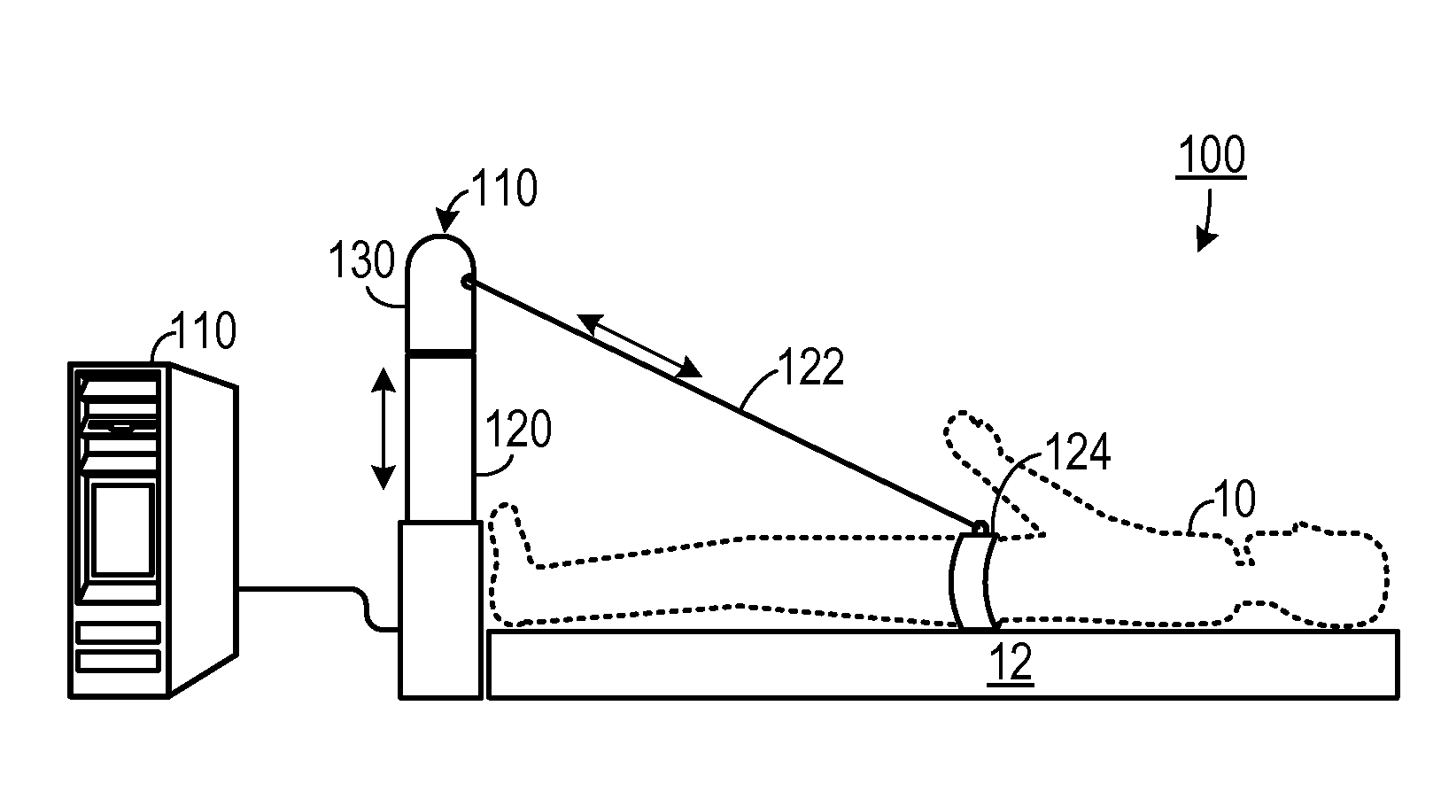
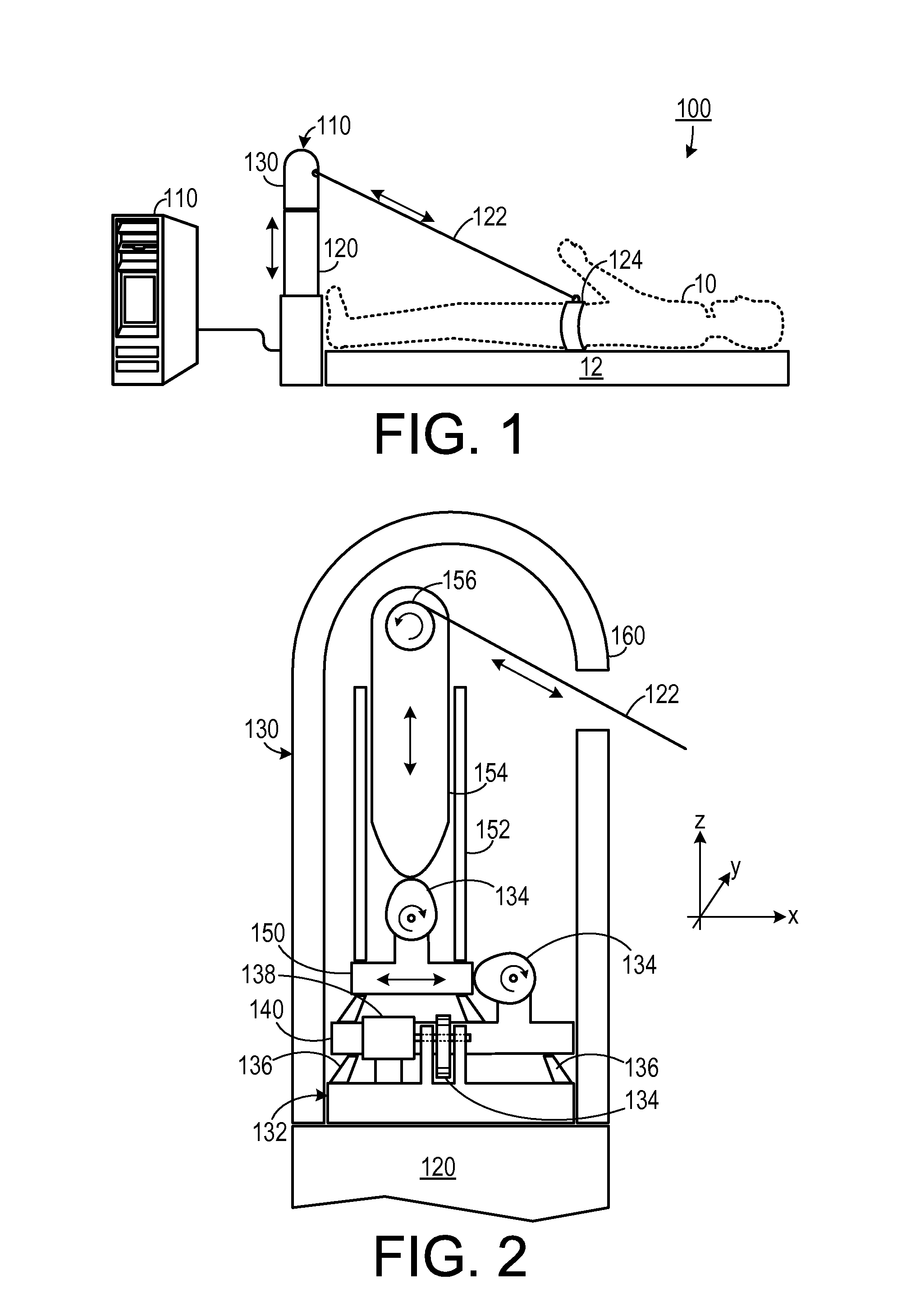
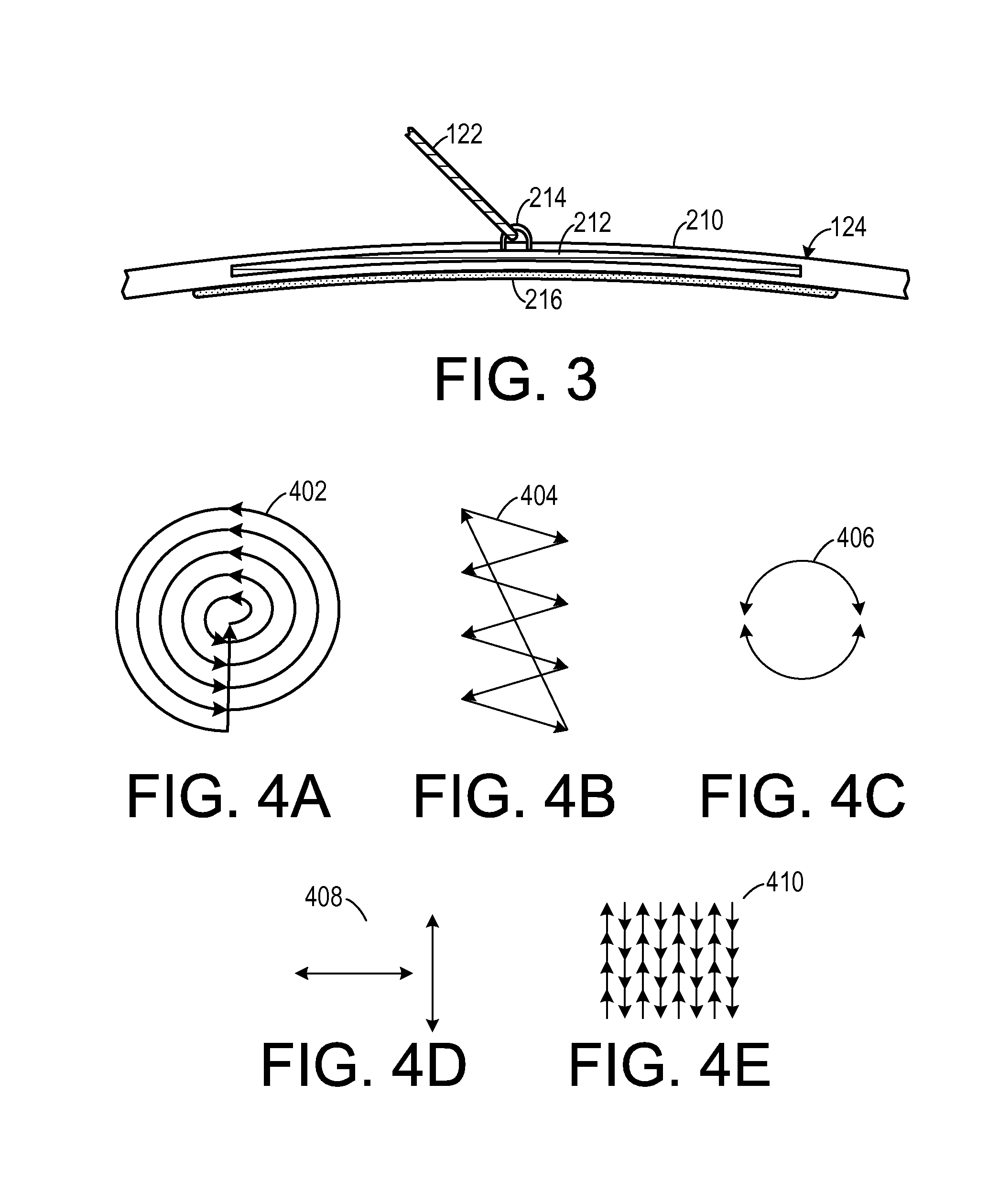
[0007]The disadvantages of the prior art are overcome by the present invention which, in one aspect, is a spinal treatment system for applying a preselected force regimen to a spine of a patient. A treatment bed, having a head end and a foot end, is configured to support the patient. A harness is configured to transmit force to a portion of the spine of the patient. A cable having a first end is coupled to the harness and is configured to apply force to the harness.

Problems solved by technology

The simple oscillation patterns, however, tend to relax only certain muscles in the spinal area and, thus, fail to achieve complete relaxation quickly.

Method used


Image

  • Spinal distraction device with three dimensionally vibrating matrix head
  • Spinal distraction device with three dimensionally vibrating matrix head
  • Spinal distraction device with three dimensionally vibrating matrix head

Examples


Embodiment Construction

[0015]A preferred embodiment of the invention is now described in detail. Referring to the drawings, like numbers indicate like parts throughout the views. As used in the description herein and throughout the claims, the following terms take the meanings explicitly associated herein, unless the context clearly dictates otherwise: the meaning of “a,”“an,” and “the” includes plural reference, the meaning of “in” includes “in” and “on.”

[0016]As shown in FIG. 1, one embodiment of the invention is a spinal treatment system 100 that includes a treatment bed 12 upon which a patient 10 reclines and a spinal distraction device 110 that includes a mechanism 120 for adjusting a vertical displacement of a matrix head 130, thereby adjusting the angle at which force is applied to the patient 10 through a cable 122 (such as a steel cable). The cable 122 applies force to a harness 124 that transfers the force to the patient 10. The matrix head 130 is controlled by a computer 110, which controls the...


PUM


Abstract

A spinal treatment system for applying a preselected force regimen to a spine of a patient includes a treatment bed, having a head end and a foot end, is configured to support the patient. A harness is configured to transmit force to a portion of the spine of the patient. A cable having a first end is coupled to the harness and is configured to apply force to the harness. A matrix head is coupled to the cable and is configured to apply a force, having a force magnitude and a force direction, to the cable, so that the force direction varies along more than one axis. A vertical displacement drive is disposed adjacent to the foot end of the treatment bed and is configured to support the matrix head and to displace the matrix head along a vertical axis. A computer is programmed to drive the vertical displacement drive and the matrix head.

Description

CROSS-REFERENCE TO RELATED APPLICATION(S)[0001]This application claims the benefit of U.S. Provisional Patent Application Ser. No. 60 / 887,953, filed Feb. 2, 2007, the entirety of which is hereby incorporated herein by reference.BACKGROUND OF THE INVENTION[0002]1. Field of the Invention[0003]The present invention relates to medical devices and, more specifically, to a device for applying forces to a patients spine.[0004]2. Description of the Prior Art[0005]Spinal distraction devices treat lower back pain by applying a decompression force to selected vertebrae of a patient. Existing spinal distraction devices apply either a static force on the patent or a simple oscillating force to the patient. The use of oscillations allows the patient to relax while the force is being applied, thereby facilitating the treatment. The simple oscillation patterns, however, tend to relax only certain muscles in the spinal area and, thus, fail to achieve complete relaxation quickly. Complete relaxation ...

Claims


Application Information

Patent Timeline
IPC IPC(8): A61H1/00A61F5/00
CPCA61H1/0218A61H1/0292A61H23/0254A61H2001/0233A61H2201/0192A61H2201/1418A61H2205/081A61H2201/1623A61H2201/163A61H2201/164A61H2201/165A61H2201/5007A61H2203/0443A61H2201/1604
Inventor BECERRA, CARLOS
Owner NORTH AMERICAN MEDICAL CORPORTAION
Learn More