Eureka AIR delivers breakthrough ideas for toughest innovation challenges, trusted by R&D personnel around the world.

Percussion Hammer and/or Drill Hammer Comprising a Handle Which Can be Guided in a Linear Manner

a technology of percussion hammer and handle, which is applied in the direction of manufacturing tools, percussive tools, portable percussive tools, etc., can solve the problems of increased constructive expense and additional constructive space, and achieve the effect of reducing constructive expense and improving vibration-damping properties

Inactive Publication Date: 2008-08-14
WACKER NEUSON SE
View PDF26 Cites 12 Cited by
  • Summary
  • Abstract
  • Description
  • Claims
  • Application Information

AI Technical Summary

Benefits of technology

[0008]The underlying object of the present invention is to indicate a percussion hammer and / or drill hammer having a guide device that is improved with respect to its guide action for the linear guiding of a handle device relative to a hammer housing, with simultaneous maintenance or improvement of vibration-damping properties, and a reduction of the constructive expense.

Problems solved by technology

Nonetheless, their realization requires additional constructive space, and an additional constructive expense resulting from an increased number of individual parts.

Method used


Image

  • Percussion Hammer and/or Drill Hammer Comprising a Handle Which Can be Guided in a Linear Manner
  • Percussion Hammer and/or Drill Hammer Comprising a Handle Which Can be Guided in a Linear Manner
  • Percussion Hammer and/or Drill Hammer Comprising a Handle Which Can be Guided in a Linear Manner

Examples


Embodiment Construction

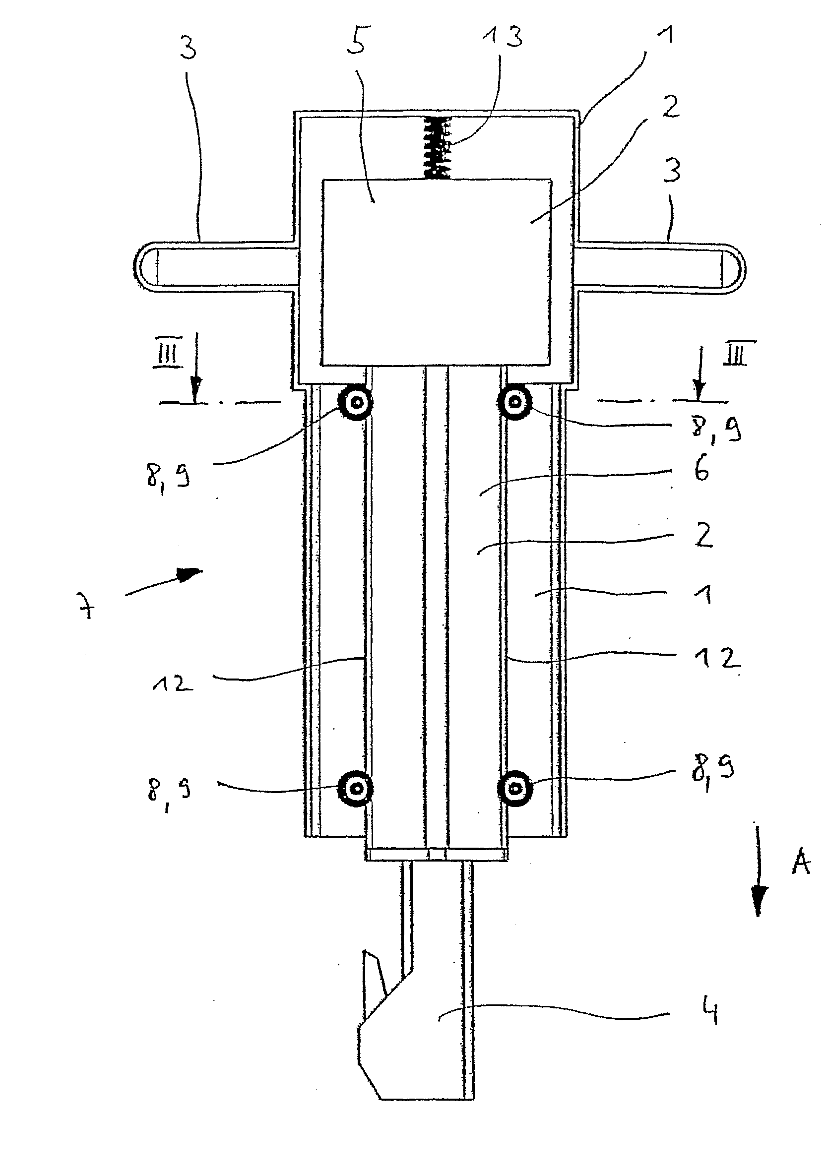
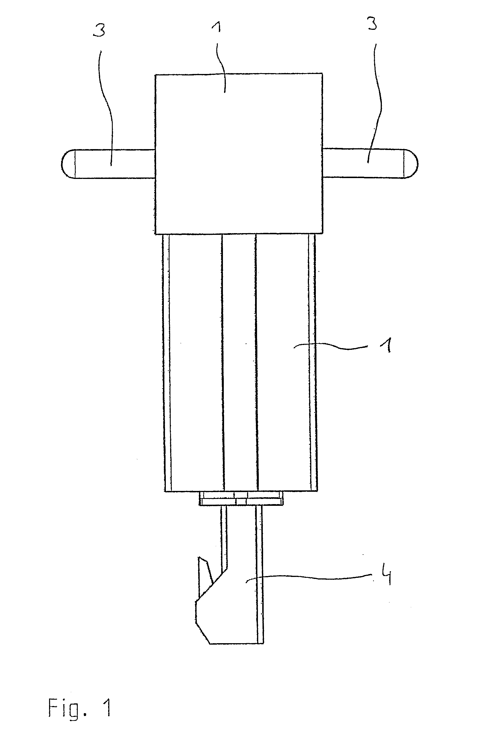
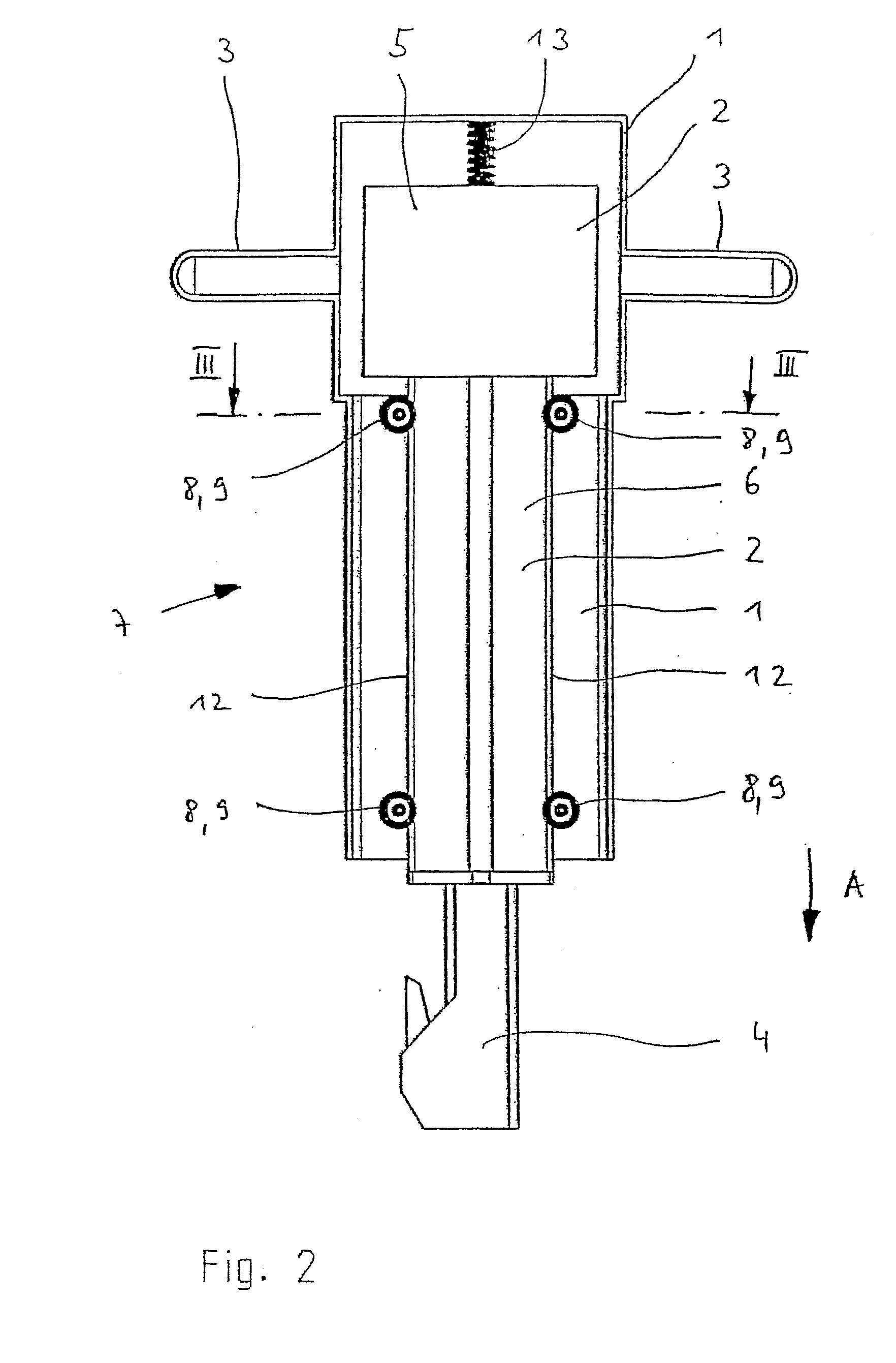
[0027]FIG. 1 shows a schematic side view of a percussion hammer and / or drill hammer according to the present invention, designated “hammer” in the following. FIG. 2 shows the same view, except that a front part of a handle cover 1 acting as a handle device has been removed, so that a schematically represented hammer housing 2 is visible in the interior.

[0028]Two handles 3 by which an operator can hold the hammer are attached to the outside of handle cover 1. At the lower end of handle cover 1 or of hammer housing 2, there opens a tool receptacle 4 in which a tool, e.g. a drill or a chisel, can be fastened in a known manner.

[0029]Such a design is already known in principle from DE 34 47 401 A1.

[0030]Hammer housing 2 has a drive housing 5 in which a motoric drive, a crank drive, etc., are provided in a known manner. Underneath drive housing 5, a percussion housing 6 is situated that is also part of hammer housing 2, and in which, from the drive movement produced by the motor, an impac...


PUM


Abstract

The invention relates to a percussion hammer and / or a drill hammer comprising a hammer housing, a handle which is preferably embodied as a handle cover and which can be displaced in a working direction (A) in relation to the hammer housing and which surrounds at least one part of the hammer housing. The hammer also comprises a guiding device which is used to guide the handle cover in a linear manner in relation to the hammer housing. The hammer is characterized in that the guiding device comprises a rolling body device which is active between the hammer housing and the handle cover. The rolling body device ensures that the handle cover is guided in a stable manner, with respect to tilting, in relation to the hammer housing.

Description

BACKGROUND OF THE INVENTION[0001]1. Field of the Invention[0002]The present invention relates to a percussion hammer and / or drill hammer according to the preamble of patent claim 1.[0003]2. Description of the Related Art[0004]Such a percussion hammer and / or drill hammer, designated “hammer” hereinafter, is known from DE 34 47 401 A1. According to this document, a part of a hammer housing in which there are situated, inter alia, a drive mechanism of the hammer and a percussion mechanism driven by the drive mechanism, is surrounded by a handle device that is realized as a handle cover. On the handle cover, handles are provided for the operator. A guide device made up of parallel rocker arms enables the handle cover to be displaced in linear fashion relative to the hammer housing when the operator presses the hammer, via the handles, against the stone that is to be processed. The parallel rockers are further connected to torsion springs in order to enable an oscillation damping for the...

Claims


Application Information

Patent Timeline
IPC IPC(8): B25D17/04
CPCB25D17/043B25D2250/371B25D2250/331B25D2250/121B25D17/24
Inventor BERGER, RUDOLFSCHMID, WOLFGANG
Owner WACKER NEUSON SE
Why Eureka
Eureka Blog
Learn More