Elevator Climbing System

a technology of climbing system and elevator, which is applied in the direction of elevator, building aid, construction, etc., can solve the problems of spring disengagement of brake pads from the rotor, increased pressure in the braking assembly, and decreased pressur

Inactive Publication Date: 2008-08-14
FRLIN SAMUEL H
View PDF50 Cites 34 Cited by
  • Summary
  • Abstract
  • Description
  • Claims
  • Application Information

AI Technical Summary

Benefits of technology

[0022]The cantilevered overhang may be a self-contained, portable cantilevered bracket assembly. The cantilevered bracket assembly may include a pair of substantially vertical, triangular support members aligned in parallel and a substantially horizontal support bar having opposing ends attached to the triangular support members. The triangular support members may include at least one latch allowing the cantilevered bracket assembly to be removably securable to an adjacent structure. The roller chains may be attached to the cantilevered bracket assembly. The adjacent structure may be an oil derrick, a building, a water tower, a TV or radio tower, a ship or other structure requiring the elevator climbing system. The cantilevered bracket assembly provides for proper alignment between the sprockets and the respective roller chains.

Problems solved by technology

A depressible brake release pedal may be connected in communication with the actuator, such that depression of the brake release pedal causes actuation of the actuator resulting in increased pressure in the braking assembly, which in turn causes the spring to disengage the brake pads from the rotor.
Activation of the limit switch opens a valve on the calipers for a predetermined time releasing brake fluid from the caliper directly to the brake fluid reservoir resulting in decreased pressure and causing the spring to engage the brake pads with the rotor.

Method used


Image

  • Elevator Climbing System
  • Elevator Climbing System
  • Elevator Climbing System

Examples


Embodiment Construction

[0042]The devices discussed herein are merely illustrative of specific manners in which to make and use this invention and are not to be interpreted as limiting in scope.

[0043]While the devices have been described with a certain degree of particularity, it is to be noted that many modifications may be made in the details of the construction and the arrangement of the devices and components without departing from the spirit and scope of this disclosure. It is understood that the devices are not limited to the embodiments set forth herein for purposes of exemplification.

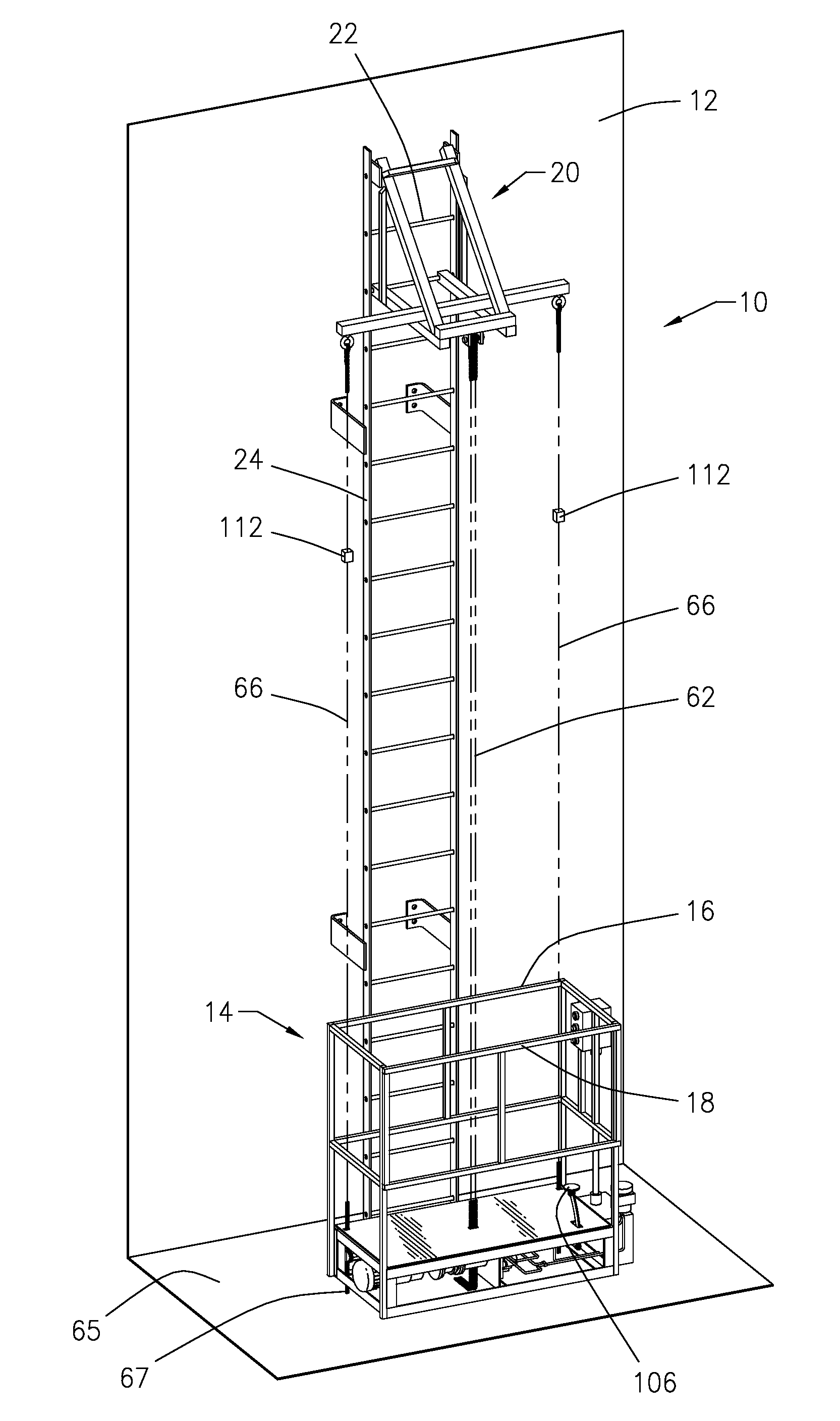
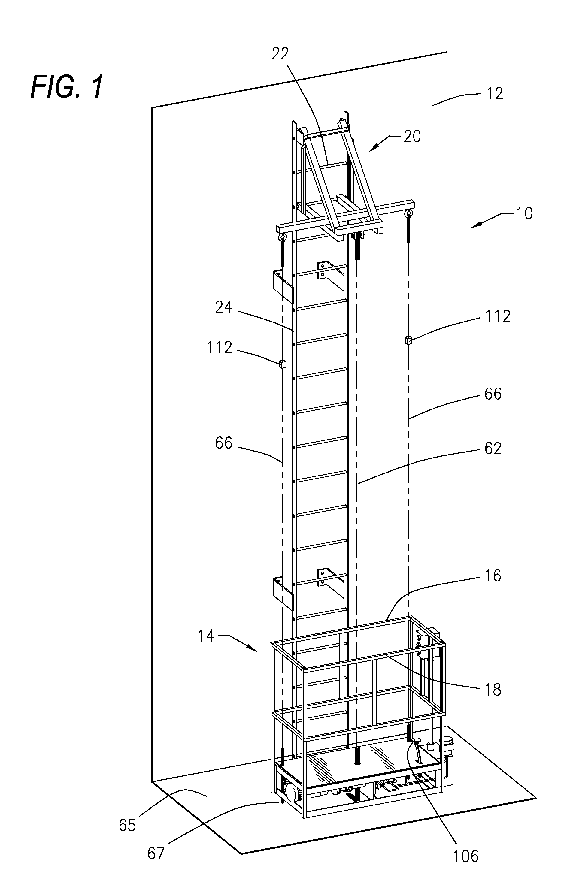
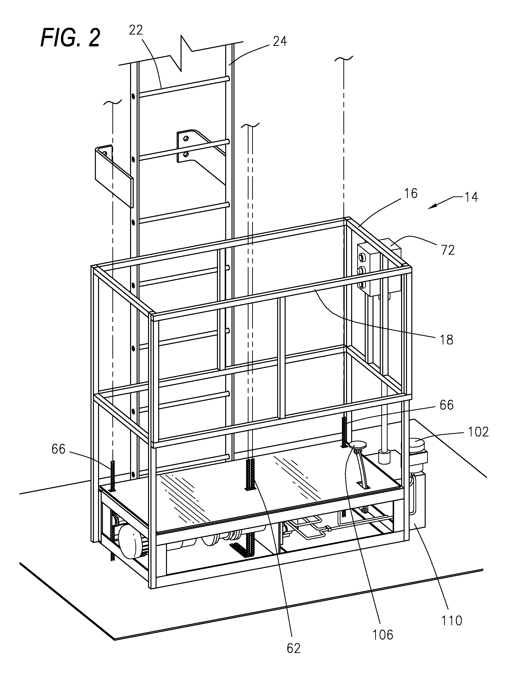
[0044]Referring to the figures of the drawings, wherein like numerals of reference designate like elements throughout the several views, and initially to FIG. 1, an elevator climbing system 10 that is self-contained and portable, and which is removably securable to a cantilevered overhang on an adjacent structure 12. The elevator climbing system 10 may include an elevator car or platform 14. The elevator car 14 may inc...


PUM


Abstract

A portable elevator climbing system removably attachable to a cantilevered overhang on an adjacent structure, whereby an elevator car travels up and down a plurality of roller chains. The roller chains are engaged with sprockets and guide rollers attached to an axle driven by a motor. The orientation and alignment of the sprockets, guide rollers and roller chains provide for a stable elevator car and for a system free of backlash in both directions. The elevator climbing system includes a dampening assembly to control the rate of decent in the event of transmission, motor or other failure. The elevator climbing system may be controlled so that the start and stop of the motor is coordinated with the release and application of a braking assembly. The efficiency of the elevator climbing system may be varied by adjusting the offset between the sprockets and the guide rollers.

Description

CROSS-REFERENCE TO RELATED APPLICATIONS[0001]This application claims priority to and is a continuation-in-part of U.S. application Ser. No. 10 / 760,751, filed Jan. 20, 2004, which is incorporated herein by reference.BACKGROUND OF THE INVENTION[0002]1. Field of the Invention[0003]This invention relates generally to an elevator climbing system, and more particularly concerns a portable elevator climbing system removably attachable to a cantilevered overhang on an adjacent structure, wherein an elevator car travels up and down a plurality of roller chains.[0004]2. Description of the Related Art[0005]Elevators, trams and other devices for transporting items and people up and down steep slopes and vertically through buildings are known. There has always been a danger that, should the device fail, the elevator car or tram would fall a great distance resulting in damage to goods and death to passengers. Several devices have been designed to operate as brakes to stop a rapidly descending car...

Claims


Application Information

Patent Timeline
Patent Type & Authority Applications(United States)
IPC IPC(8): B66B11/04
CPCB66B9/027E06C7/12B66B9/187
Inventor FRANKLIN, SAMUEL H.
Owner FRLIN SAMUEL H
Why Eureka
Try Eureka