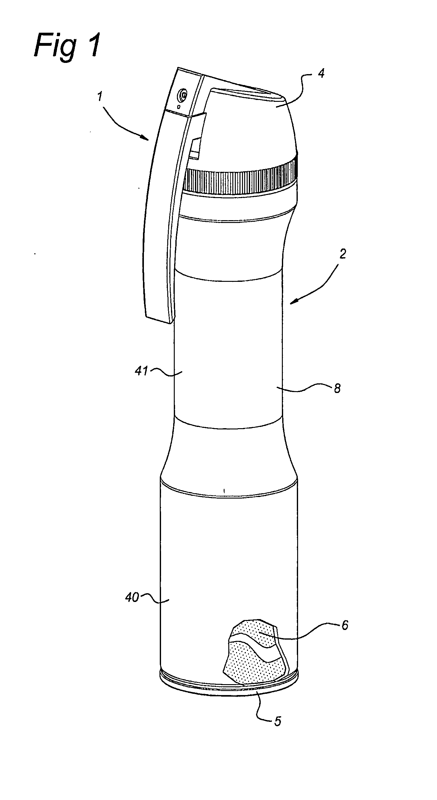
[0010]a dispensing cap mounted on the top of the container.The dispensing cap of the dispensing device according to the invention carries: a
nozzle debauching outside the cap for spraying the product, the nozzle being connected to the valve mechanism by a conduit; as well as an actuating member having a horizontal arm and a vertical arm, the
horizontal and vertical arm being rigidly connected to each other. The terms vertical and horizontal arm are related to the dispensing device considered in upright standing condition. The vertical arm extends in the axial direction of the container with its free end facing downwards. The horizontal arm is hingedly suspended in the cap and engages the valve mechanism to actuate the valve mechanism upon pulling the vertical arm towards the body portion. The body portion can be seen as divided into a lower portion and an upper portion, the upper portion of the body portion comprising a one-hand grip. The “upper portion comprising a one-hand grip” is to be understood as dimensioned so that the dispensing device can be held by one-hand gripping around the one-hand grip provided at the upper portion of the body portion of the container. In order to be able to operate the actuating member with the same hand, the vertical arm is arranged to be engagable by at least one finger of the hand gripping the one-hand grip. According to the invention the one-hand grip is in its circumference constricted with respect to the lower portion. This means that the circumference of the upper portion is smaller than the circumference of the lower portion and that consequently the lower portion has a volume per
axial length—of the container—unit which is larger than the volume per
axial length unit of the upper portion. By configuring the container body in this manner, the centre of gravity of the dispensing device is—considered with respect to prior art devices having a container of the same volume—shifted downwards towards the bottom of the container without increasing the
axial length of container being required. The device is thus easy to
handle. Assuming that during dispensing the top of the container is directed upwards—which is for this kind of dispensing devices advisable—this means that the hand holding and actuating the dispensing device can be held more stable. A dispensing device which is easier held stable enables a more accurate aiming of the nozzle at the target.
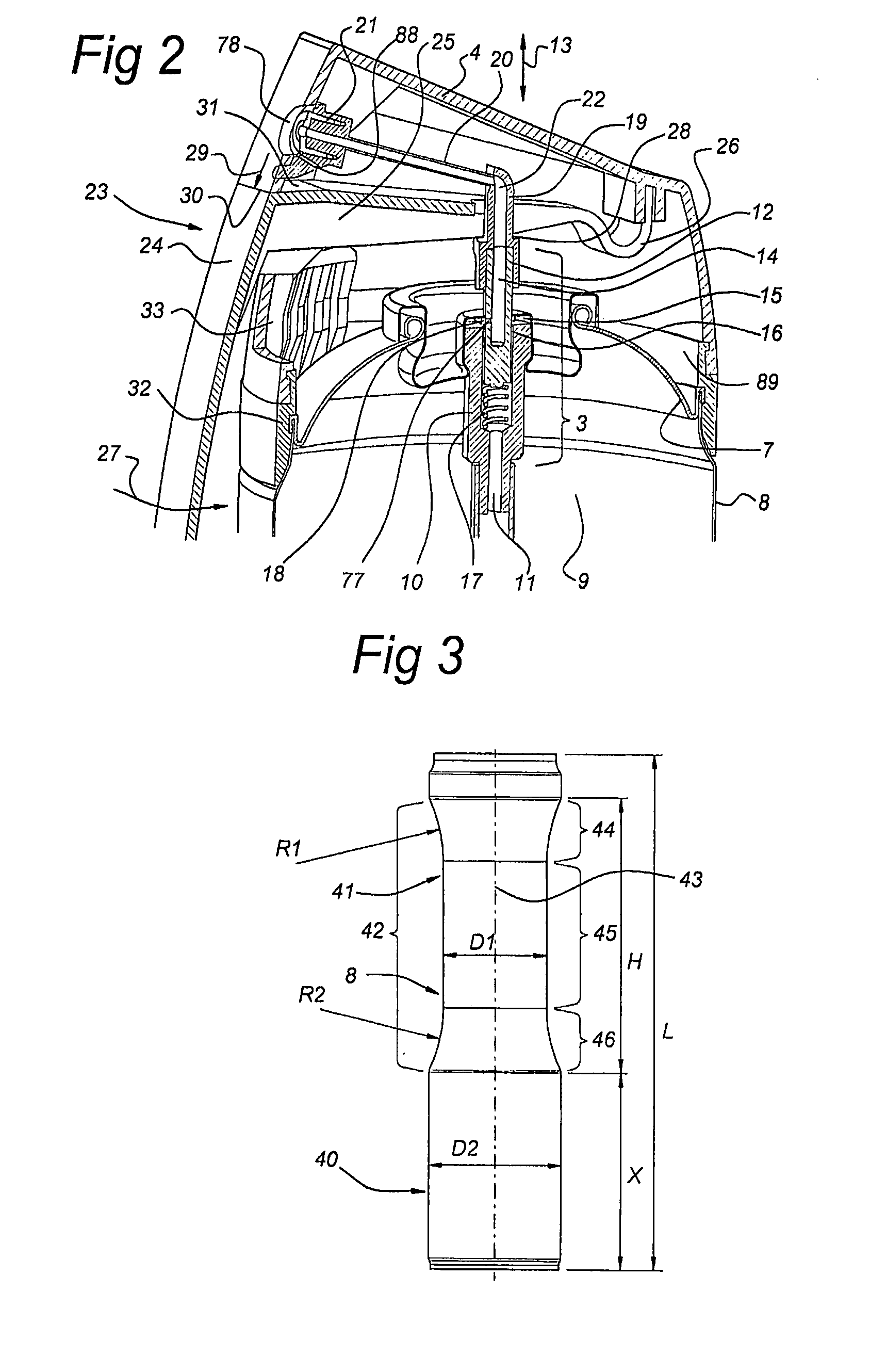
[0011]The holding stability and thus the accuracy of aiming at a target can be further improved when the upper end of the one hand grip widens with respect to the centre of the one-hand grip to provide a supporting surface adapted for resting on the upper part of a hand gripping around the one-hand grip. The widening of the upper and of the one hand grip following, viewed in the axial direction, a continuous curvature, provides this
advantage that the dispensing device lies more comfortable in the hand, which contributes in the aiming accuracy. This comfort is improved when the continuous curvature has a
radius between 55 and 75 mm, preferably between 60 and 72 mm. The comfort of use is further improved when the lower end of the one-hand grip also widens with respect to the centre of the one-hand grip to provide a supporting surface, in this case adapted for supporting the lower part of a hand gripping around the one-hand grip. Also in this case it is advantageous when this widening of the lower end of the one-hand grip follows, viewed in the axial direction, a continuous curvature. Preferably this continuous curvature at the lower end of the one-hand grip has a
radius between 55 and 75 mm, preferably between 60 and 72 mm. The lower end of the one-hand grip and the upper hand of the one-hand grip can thus be shaped mirror symmetrically.
[0013]According to the invention it is further advantageous when the circumference of the centre of the one-hand grip is at most 190 mm, preferably at most 180 mm, more preferably at most 170 mm. A circumference of at most 190 mm, corresponding to a circle
diameter of about 60-61 mm, provides a one-hand grip, which can be held good by a male hand of above
average size, and which can also be held by a male hand of
average size. A circumference of at most 180 mm, corresponding to a circle
diameter of about 57 mm, provides a one-hand grip which can be held very solidly by a male hand of above
average size, and which can be held good by a male hand of average size. A circumference of at most 170 mm, corresponding to circle
diameter of about 54-55 mm, provides a
solid grip for a male hand of average size.
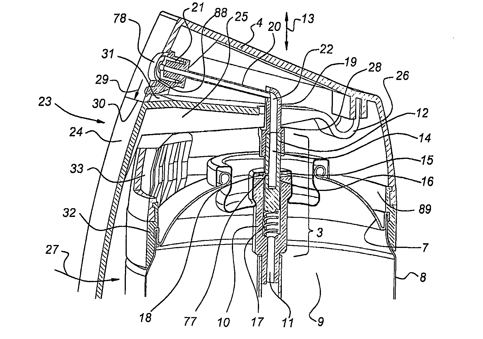
[0016]According to a further advantageous embodiment of the invention, the nozzle is fixed with respect to the cap. A nozzle fixed with respect to the cap prevents the nozzle from moving together with the actuating member, which would make aiming of the nozzle at the target less accurate.
[0017]According to a further embodiment of the invention, the vertical arm of the actuating member is arranged essentially below the nozzle. Arranging the vertical arm essentially below the nozzle enables accurately aiming the nozzle at the target. A further
advantage is that drips of products originating from the nozzle can be collected on the horizontal arm—not only when the device is held upright but also when the device is held in a slanting position—. Drips collected on the horizontal arm can—when the device is held upright—be guided into the cap so that the user is prevented from contacting. In this respect it is of additional
advantage when the horizontal arm projects from the cap. In this respect it is to be noted that only a slight projection of about 0.5 mm is sufficient. According to a further advantageous embodiment, which optionally can advantageously be applied with the vertical and / or horizontal arm arranged essentially below the nozzle, the nozzle is arranged submerged in a recess formed in the cap. A submerged arrangement of the nozzle in the cap provides collection means for small drips
coming out of the nozzle at the start or at end of a spraying action. The submerged recess will provide for retainment of the small drips in the recess so that the hand of the user is prevented from contacting the drips. Advantageously the recess containing the submerged nozzle will be in liquid communication with the hollow internal of the cap, so that drips of product, such as paint, can flow into the cap where they do not harm. The hands of the user are thus being protected against becoming dirty.
[0019]In order to prevent inadvertently spraying, the container is, at its top, provided with a stop and the actuating member is around the axial direction rotatable with respect to the stop between a locked position in which the stop lies under the horizontal arm of the actuating member to prevent movement of the actuating member and an unlocked position in which the stop lies beside the actuating member to allow movement of the actuating member. By rotating the stop and the actuating member with respect to each other, one can prevent the actuating member from any movement as well as allow actuating of the actuating member.

