Safety Steering Column for a Motor Vehicle

Inactive Publication Date: 2008-08-14
DAIMLER AG
View PDF18 Cites 8 Cited by
  • Summary
  • Abstract
  • Description
  • Claims
  • Application Information

AI Technical Summary

Benefits of technology

[0007]One object of the invention is to provide a safety steering column of the type mentioned above, which has a simple and cost-effective design, and in which the adjustment device is substantially free from play.
[0020]In a further advantageous embodiment of the invention, a pressure element which presses the lower tube part radially against the upper tube part and thus presses the lower and upper tube parts radially against the outer tube part, is provided on the outer tube part. The pressure element is embodied, for example, as a spring or as a screw element, and ensures play-free bearing of the individual tube parts one in the other. At the same time, it makes the safety steering column rigid, thereby improving overall driving comfort.

Problems solved by technology

Furthermore, electric motors permit low-maintenance operation, are cost-effective to manufacture and have a long service life due to high production quality nowadays.

Method used


Image

  • Safety Steering Column for a Motor Vehicle
  • Safety Steering Column for a Motor Vehicle
  • Safety Steering Column for a Motor Vehicle

Examples


Embodiment Construction

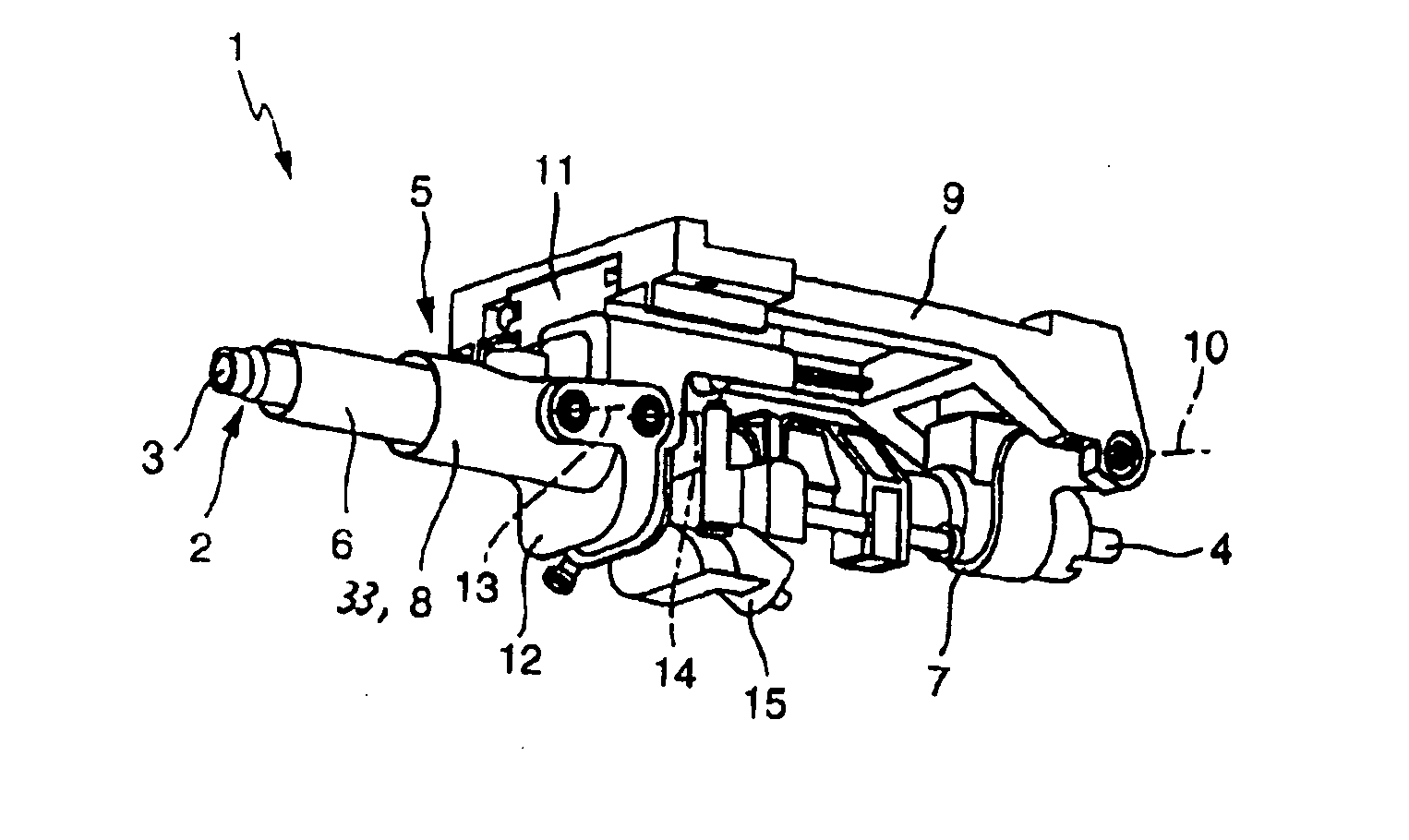
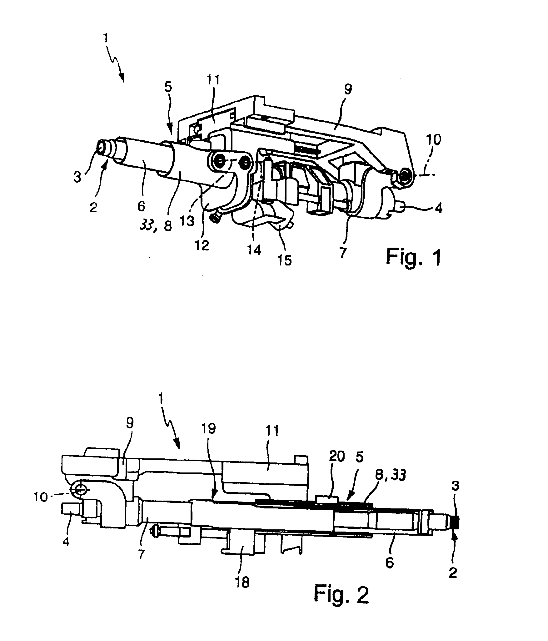
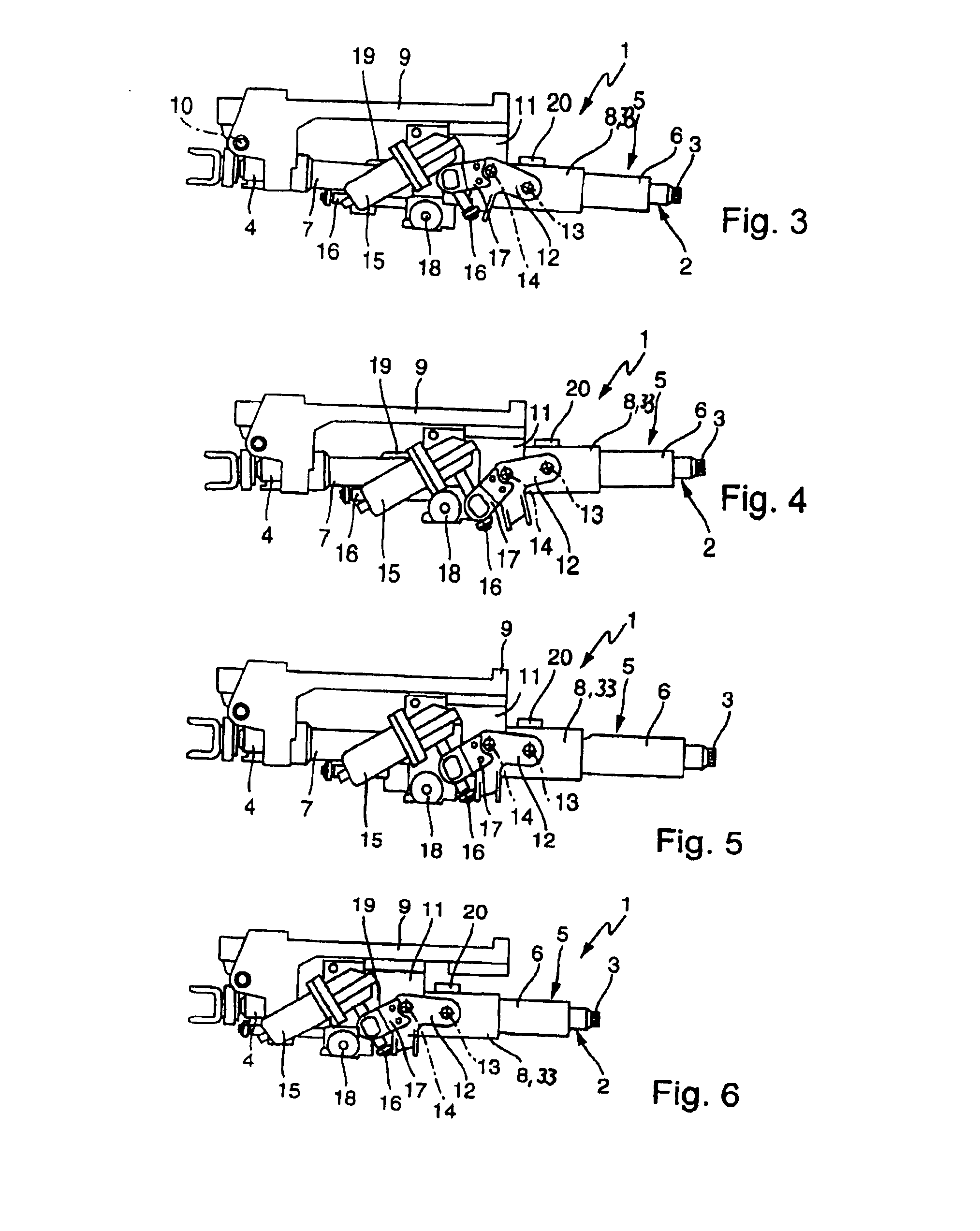
[0031]According to FIG. 1, a safety steering column 1 has a telescopic steering spindle 2 which is composed of an upper spindle part 3 near to the steering wheel and a lower spindle part 4 remote from the steering wheel. The spindle is rotatably mounted in a jacket tube 5 with a total of three parts. The jacket tube 5 is also of telescopic design and has an upper tube part 6 near to the steering wheel, a lower tube part 7 remote from the steering wheel and an outer tube part 8. The outer tube part 8 forms a force transmitting element 33 during the vertical adjustment of the safety steering column 1, on which further details will be given later.

[0032]The safety steering column 1 is usually installed in a motor vehicle and is mounted by means of a guide on a bracket 9 which is fixed to the vehicle. In order to vertically adjust the safety steering column 1 and a steering handle (not illustrated) arranged at the end of the upper spindle part 3, the lower tube part 7 is mounted pivotabl...


PUM


Abstract

A safety steering column (1) is provided for a motor vehicle, which has a telescopic steering spindle (2) with an upper spindle part (3) which is near to the steering wheel and a lower spindle part (4) which is remote from the steering wheel, and is rotatably mounted in a jacket tube (5). The jacket tube (5) is of telescopic design and has an upper tube part (6) which is near to the steering wheel and a lower tube part (7) which is remote from the steering wheel, the lower tube part (7) being mounted so as to be pivotable about a first axis (10) on a bracket (9) which can be arranged fixed to the vehicle. In addition, an adjustment device which serves to vertically adjust the safety steering column (1) and has an actuating element (12) which is mounted so as to be pivotable about a second axis (14) is provided. The safety steering column (1) is distinguished by the fact that the actuating element (12) is coupled to the jacket tube (5) by means of a force transmitting element (33) which can be adjusted in a translatory fashion in the axial direction relative to the jacket tube (5).

Description

BACKGROUND AND SUMMARY OF THE INVENTION[0001]This application claims the priority of German patent document 10 2004 020 048.3, filed Apr. 23, 2004 (PCT International Application No. PCT / EP2005 / 004324, filed Apr. 22, 2005), the disclosure of which is expressly incorporated by reference herein.[0002]The present invention relates to a safety steering column for a motor vehicle.[0003]Safety steering columns, which are common in contemporary motor vehicle engineering, protect a driver of the motor vehicle in the event of an accident by moving out of a hazardous area of the vehicle in an active or passive fashion. In an active safety steering column, this movement is carried out automatically so that the driver normally does not impact against a steering handle which is arranged at an upper end of the steering column. A passive safety column can be moved out of the hazardous area when a predefined force is exceeded; for example an upper steering column part may be mounted so as to be axia...

Claims


Application Information

Patent Timeline
IPC IPC(8): B62D1/18B62D1/181
CPCB62D1/181
Inventor BECHTEL, TRAVISBOHLEN, JENSBORN, CHRISTIANBROWN, MARKUSDUNCAN, SCOTT D.EGGERS, FREDHEBENSTREIT, AXELKNOLL, KARL-HEINZVON EY, PETER
Owner DAIMLER AG
Why Eureka
Try Eureka