Image forming apparatus, image processing apparatus, and control method therefor

a technology of image processing and forming apparatus, which is applied in the direction of digitally marking record carriers, visual presentation using printers, instruments, etc., can solve the problems of affecting the amount and direction of ink to be discharged, degrading image quality, and periodically occurrence of blank portions, so as to reduce density unevenness and improve image quality

Inactive Publication Date: 2008-08-14
CANON KK
View PDF21 Cites 15 Cited by
  • Summary
  • Abstract
  • Description
  • Claims
  • Application Information

AI Technical Summary

Benefits of technology

[0021]The present invention has been made to solve the above problems, and has as its object to provide an image forming apparatus, an image processing apparatus, and a control method therefor which have the following functions. That is, the present invention achieves an improvement in image quality by reducing density unevenness due to variations in printing elements, graininess due to a feeding amount error, and long-period density unevenness in multi-pass printing.

Problems solved by technology

For example, a slight error in the process of manufacturing a printhead such as variations in the shape of the orifices of a printhead, discharge heaters, or piezoelectric elements greatly affects the discharge amount and direction of ink to be discharged.
That is, such a slight error is a factor that causes density unevenness in the image to be formed and degrades the image quality.
As a result, blank portions periodically exist in the head main scanning direction, or dots are excessively superimposed in some portions.
Even if, however, such multi-pass printing is performed, the problem of density unevenness may not be easily solved depending on the printing ratio of each printing scan.
However, according to this method, since an image is formed in each main scan, if a sheet feeding error occurs, the graininess of an image deteriorates, and hence the image quality of the output image deteriorates.
If, however, as shown in FIG. 55, the feeding of the print medium shifts in the arrow direction before the second pass printing, the image formed on the print medium deteriorates and becomes grainy.
In addition, since the sheet feeding error amount varies for each sheet feeding operation, the following problem arises.
The following problem arises in the above method of reducing image quality deterioration in the leading and trailing edge areas of a recording member in the feeding direction by changing the number of nozzles of the printhead which are to be used in one printing scan.
This may make it impossible to efficiently use a limited number of nozzles.

Method used


Image

  • Image forming apparatus, image processing apparatus, and control method therefor
  • Image forming apparatus, image processing apparatus, and control method therefor
  • Image forming apparatus, image processing apparatus, and control method therefor

Examples


first embodiment

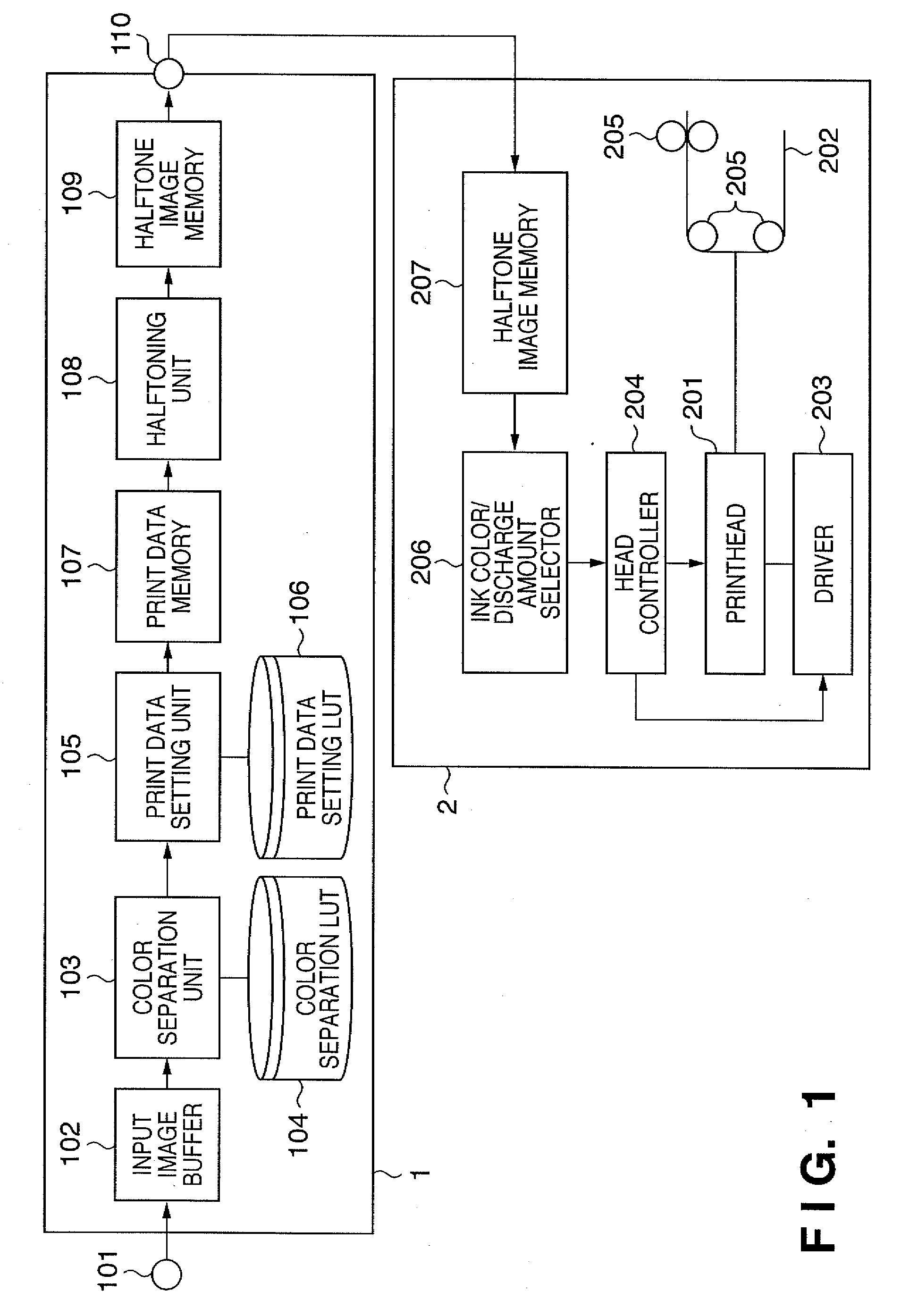
[0084]FIG. 1 is a block diagram showing the arrangement of an image forming system according to this embodiment. Referring to FIG. 1, reference numeral 1 denotes an image processing apparatus; and 2, a printer. Note that the image processing apparatus 1 can be implemented by a printer driver installed in a general personal computer. In this case, each unit of the image processing apparatus 1 to be described below is implemented by making a computer execute a predetermined program. Another arrangement is, for example, an arrangement in which the printer 2 includes the image processing apparatus 1.

[0085]The image processing apparatus 1 and the printer 2 are connected to each other via a printer interface or a network interface. The image processing apparatus 1 receives image data to be printed via an image data input terminal 101, and stores the data in an input image buffer 102. A color separation unit 103 color-separates the input image data into data corresponding to the ink colors...

second embodiment

[0194]The second embodiment of the present invention will be described below.

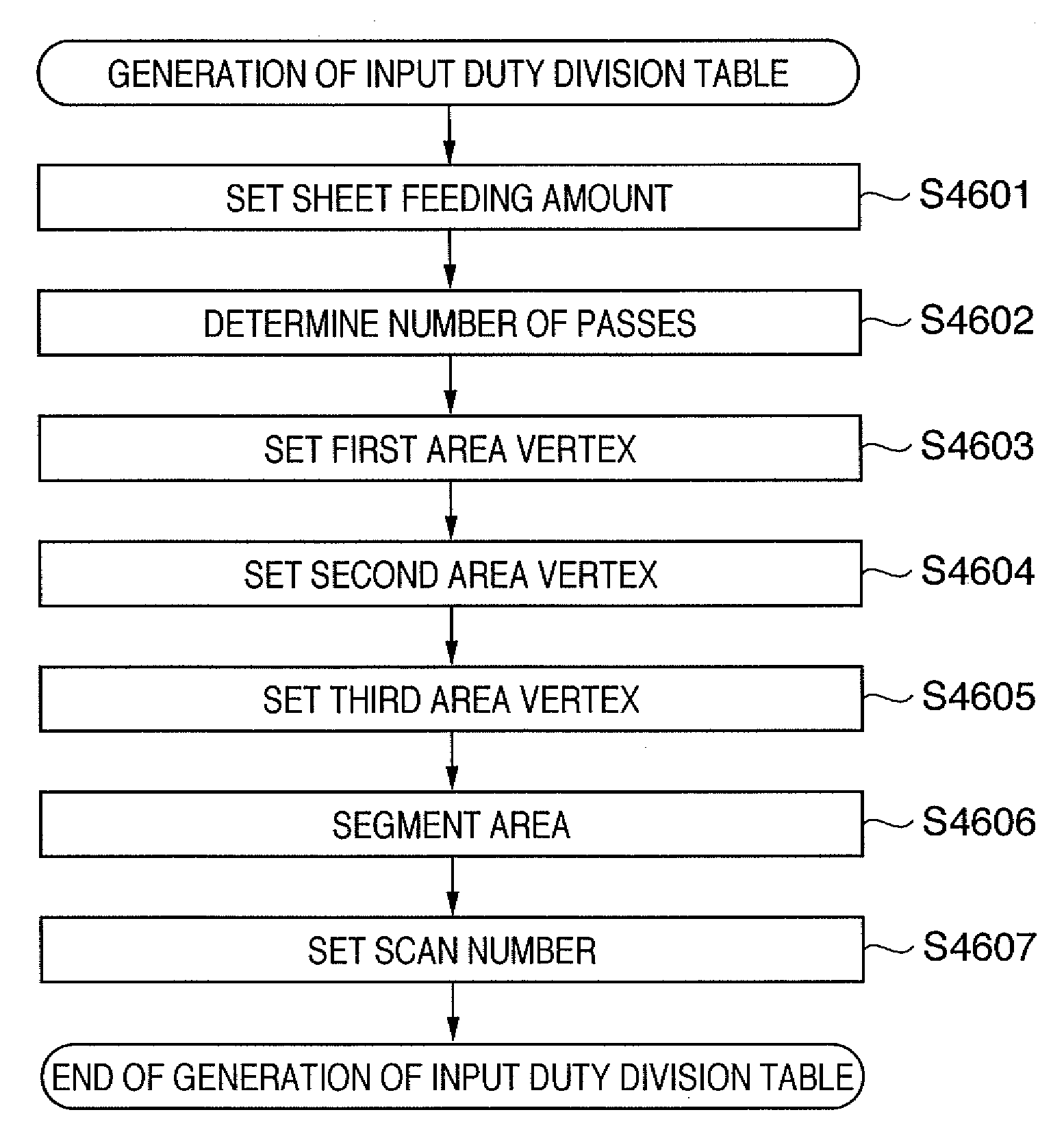
[0195]The first embodiment has exemplified the case in which in the multi-pass printing method, the number of passes for completing a print area in the main scanning direction of an image is constant (e.g., four passes). The second embodiment exemplifies a case in which the number of passes is variable. Note that the arrangement of an image forming apparatus of the second embodiment is the same as that of the first embodiment, and hence a repetitive description will be omitted.

[0196]The number of passes in the second embodiment is controlled by an input duty division table. That is, a characteristic feature of the second embodiment is that the number of passes can be set in accordance with an input duty division table.

[0197]FIG. 32 shows an example of an input duty division table generated in the second embodiment. A print data setting LUT 106 shown in FIG. 33 is generated based on this input duty division ...

third embodiment

[0250]The third embodiment of the present invention will be described below.

[0251]The first and second embodiments described above have exemplified the case in which the sheet feeding amount after each scan is set in accordance with the value of the point h which segments the respective areas in the input duty division table. As in the prior art, when the sheet feeding amount is constant, density or color unevenness in the subscanning direction occurs periodically (at the period of sheet feeding). A characteristic feature of the third embodiment is that this sheet feeding amount is made to have a characteristic that makes it difficult for the human to visually perceive sheet feeding so as to make it difficult to perceive the period of unevenness. Note that the arrangement of an image forming apparatus of the third embodiment is the same as that of the first embodiment, and hence a repetitive description will be omitted.

[0252]The addition of a characteristic to a sheet feeding amount...


PUM


Abstract

In performing multi-pass printing by using a printhead having a plurality of nozzles, a print data setting unit sets a printing amount for each nozzle for each main scan of the printhead based on a print data setting LUT. This print data setting LUT reflects the information of the number of passes and the number of nozzles to be used which are arbitrarily set. A halftoning unit generates a dot pattern as a formation target by performing binarization processing for the print amounts set in this manner.

Description

BACKGROUND OF THE INVENTION[0001]1. Field of the Invention[0002]The present invention relates to an image forming apparatus, an image processing apparatus, and a control method for them and, more particularly, to an image forming apparatus, an image processing apparatus, and a control method for them, which perform image formation at a lower tone level than that of an input image.[0003]2. Description of the Related Art[0004]A general example of an image output apparatus for a word processor, personal computer, facsimile apparatus, and the like is a printing apparatus which prints information such as desired characters and images on a sheet-like print medium such as a paper sheet or film. Such printing apparatuses use various printing methods. Among them, methods of forming an image on a print medium by making ink adhere to the print medium have been widely implemented into practice. As a typical example of such methods, the inkjet printing method has been known.[0005]In order to inc...

Claims


Application Information

Patent Timeline
Patent Type & Authority Applications(United States)
IPC IPC(8): G06F15/00
CPCB41J2/2128H04N1/405G06K15/107
Inventor WATANABE, YUMI
Owner CANON KK
Why Eureka
Try Eureka