
Method for mounting electronic-component module, method for manufacturing electronic apparatus using the same, and electronic-component module

Active Publication Date: 2008-08-14
MURATA MFG CO LTD
View PDF1 Cites 8 Cited by
  • Summary
  • Abstract
  • Description
  • Claims
  • Application Information

AI Technical Summary

Benefits of technology

[0019]To overcome the problems described above, preferred embodiments of the present invention provide a method for mounting an electronic component module in which a suction head can provide a suction force and hold the electronic component module, the electronic component module can be efficiently mounted on a target board, and the height of the electronic component module mounted on the target board can be sufficiently reduced, and also provide a method for manufacturing an electronic apparatus utilizing the above-mentioned method, and an electronic component module that can sufficiently reduce the height of the electronic component module mounted on the target board.

Problems solved by technology

However, when a conventional electronic component module is mounted as shown in FIG. 14, since a gap G is required between a lower surface of a metal case 56 and upper ends of the surface mount devices including a capacitor 52a, a resistor 52b, a transistor 52c, and a coil 52d, and space is also required to accommodate the thickness T of the metal case 56, there is a problem in that the height of the resulting product is increased to a greater extent than the surface mount devices by a distance including the gap G and the thickness T.
However, since a top surface 57a of the molded resin 57 is higher than upper ends of the surface mount devices, there is still a problem in that the height of the resulting product is greater than the surface mount devices by the distance D, i.e., the distance between the top surface 57a of the molded resin 57 and the upper ends of the surface mount devices.

Method used


Image

  • Method for mounting electronic-component module, method for manufacturing electronic apparatus using the same, and electronic-component module
  • Method for mounting electronic-component module, method for manufacturing electronic apparatus using the same, and electronic-component module
  • Method for mounting electronic-component module, method for manufacturing electronic apparatus using the same, and electronic-component module

Examples


first preferred embodiment

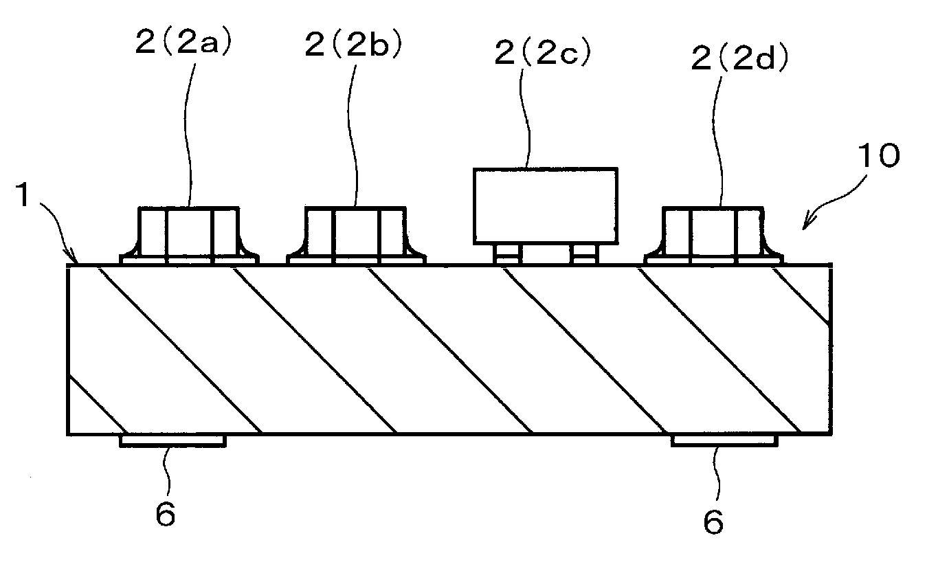
[0071]As shown in FIG. 1, an electronic component module main body 10 is prepared which includes surface mount devices 2 (for example, a capacitor 2a, a resistor 2b, a transistor 2c, a coil 2d) mounted on an upper surface of an electronic component base plate 1 (ceramic board in this preferred embodiment) having terminal electrodes 6 disposed on a lower surface thereof to be connected to a motherboard defining a target board.

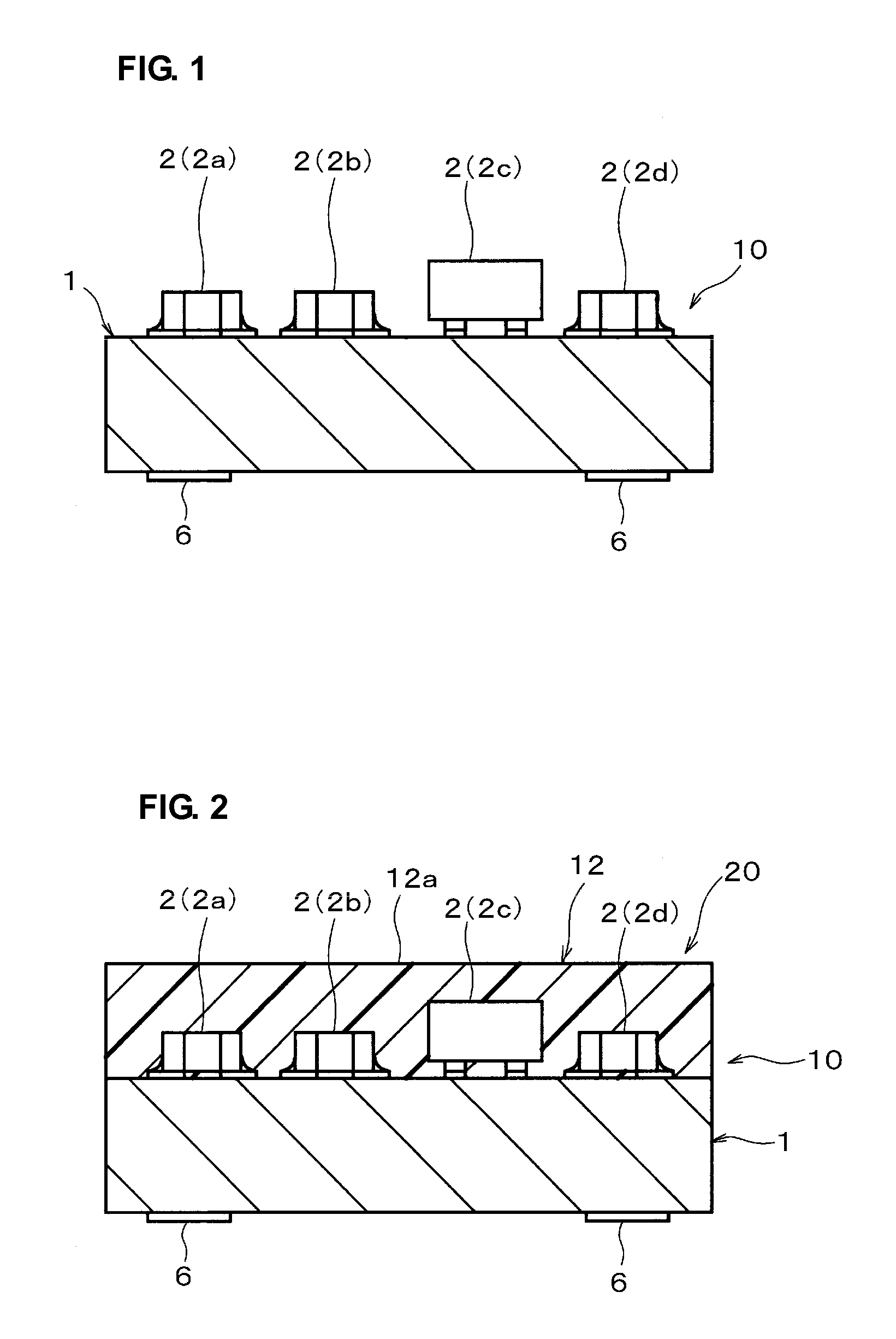
[0072]Then, naphthalene (C10H8), which is an aromatic hydrocarbon, in a liquid state is poured onto a surface of the electronic component module main body 10 having the surface mount devices 2 mounted thereon. After being solidified, a surface, or an upper surface of the solidified naphthalene shown in FIG. 2 is polished and flattened to define a suction surface member 12 having a suction surface 12a that is arranged to be held by a suction head. In such a manner, as shown in FIG. 2, an electronic component module 20 including the suction surface member 12 is ar...

second preferred embodiment

[0077]FIG. 6 shows an electronic component module 20 in accordance with a second preferred embodiment of the present invention and shows a state in which the electronic component module 20 is disposed on a motherboard. FIG. 7 shows a state in which the electronic component module 20 is mounted on a motherboard 14.

[0078]Note that, in FIGS. 6 and 7, the same reference numerals as used in FIGS. 1 to 5 denote the portions corresponding to those shown in FIGS. 1 to 5.

[0079]In the electronic component module 20 in accordance with the second preferred embodiment, a suction surface member 12 thereof is reduced in volume during reflow soldering, so that an upper end thereof is lower than an upper end of the transistor 2c, which is the tallest surface mount device mounted on an electronic component base plate 1.

[0080]Note that, according to the second preferred embodiment, the entire suction surface member 12 is not removed unlike in the first preferred embodiment. That is, the suction surfac...

third preferred embodiment

[0086]FIG. 8 is a view showing a structure of an electronic component module 20 in accordance with a third preferred embodiment of the present invention. FIG. 9 shows a state of the electronic component module 20 shown in FIG. 8, after being mounted on the motherboard 14.

[0087]Note that, in FIGS. 8 and 9, the same reference numerals as used in FIGS. 1 to 5 denote the portions corresponding to those shown in FIGS. 1 to 5.

[0088]In the electronic component module 20 in accordance with the third preferred embodiment, the suction surface member 12 thereof is made of a material that reshapes at the reflow temperature, so that a location of the upper end of the suction surface member 12 becomes lower than that of the transistor 2c, which is the tallest surface mount device, and is provided over the upper surface of the electronic component base plate 1 in a floating state so that the upper surface of the suction surface member 12 functions as a suction surface 12a for being held with the s...


PUM

PropertyMeasurementUnit
Temperatureaaaaaaaaaa
Forceaaaaaaaaaa
Volumeaaaaaaaaaa

Abstract

A suction surface member is provided on an electronic component module including an electronic component base plate and surface mount device mounted on the electronic component base plate in order to provide a suction surface at a location that is substantially at the same level as or higher than that of an upper end of a transistor that is the tallest surface mount device. The suction head adheres to the suction surface to hold the electronic component module and the electronic component module is mounted on a motherboard defining the target board. Then a treatment is performed to prevent a situation in which an upper end of the suction surface member is higher than the upper end of the tallest surface mount device mounted on the electronic component base plate.

Description

BACKGROUND OF THE INVENTION[0001]1. Field of the Invention[0002]The present invention relates to a method for mounting an electronic component module, a method for manufacturing an electronic apparatus using the method for mounting an electronic component module, and an electronic component module. Specifically, the present invention relates to a method for mounting an electronic component module which is mounted in a process in which a suction head holds the electronic component module by suction while the module is being placed on a target board, a method for manufacturing an electronic apparatus using the method for mounting an electronic component module, and an electronic component module applicable to these methods.[0003]2. Description of the Related Art[0004]FIG. 11 shows a conventional electronic component module. As shown in FIG. 11, an electronic component module 61 includes an electronic component base plate 51, which is made of a ceramic plate or other suitable material,...

Claims


Application Information

Patent Timeline
IPC IPC(8): H05K5/00H05K3/30
CPCH01L23/3121Y10T428/24917H01L25/165H01L25/50H01L2224/16H01L2924/01004H01L2924/16152H01L2924/19041H01L2924/19105H01L2924/3025H05K1/141H05K3/284H05K3/288H05K3/303H05K2201/0125H05K2203/0195H05K2203/082H05K2203/083Y10T29/4913Y10T29/49165Y10T29/49146Y10T29/49144H01L24/16H01L2224/05573H01L2224/05568H01L2924/00014H01L2224/0554Y02P70/50H01L2224/05599H01L2224/0555H01L2224/0556H05K13/04
Inventor KOYAMA, KUNIHIROYAMAMOTO, MUNEYOSHIUEJIMA, TAKANORINAKAGAWA, DAIKIMURA, MASAKI
Owner MURATA MFG CO LTD
Features
  • Generate Ideas
  • Intellectual Property
  • Life Sciences
  • Materials
  • Tech Scout
  • Unparalleled Data Quality
  • Higher Quality Content
  • 60% Fewer Hallucinations
Learn More