Method of transmitting a high-priority message in a lighting control system

a technology of lighting control system and high priority, which is applied in the field of load control system, can solve the problems of complicated installation procedure of lighting control system, limiting the number of control devices that a master device can communicate with, and complicating the installation procedur

Active Publication Date: 2008-08-14
LUTRON TECH CO LLC
View PDF67 Cites 46 Cited by
  • Summary
  • Abstract
  • Description
  • Claims
  • Application Information

AI Technical Summary

Problems solved by technology

When the lighting control systems use a high baud rate, the control devices must be wired together using specific wiring topologies, e.g., a daisy-chain topology, which complicates the installation procedure of the lighting control system.
Likewise, limiting the number of control devices that a master device can communicate with to a small number complicates the installation procedure.

Method used


Image

  • Method of transmitting a high-priority message in a lighting control system
  • Method of transmitting a high-priority message in a lighting control system
  • Method of transmitting a high-priority message in a lighting control system

Examples


second embodiment

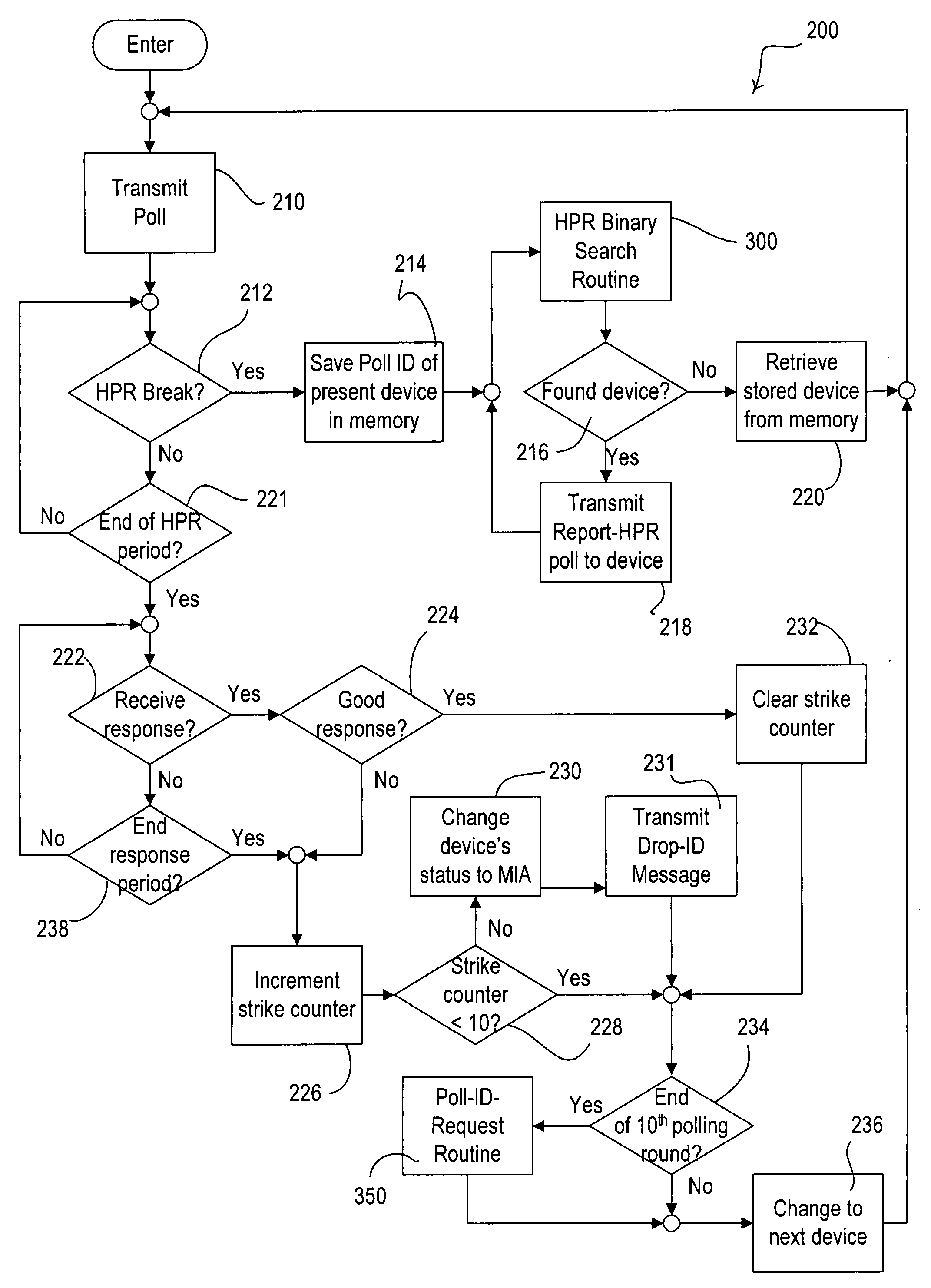
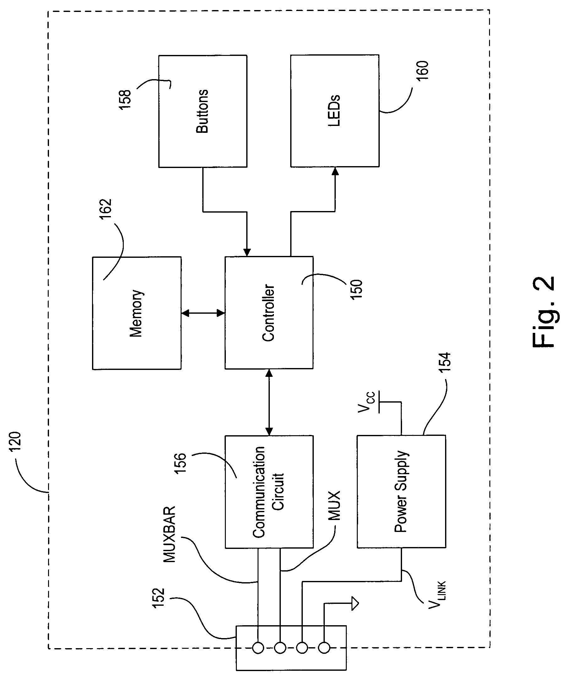
[0080]FIG. 8 is a simplified block diagram of a control device, e.g., a keypad 120′, according to the present invention. The keypad 120′ is identical to the keypad 120 shown in FIG. 2 except that the keypad 120′ includes a direct timing connection 190′ between the MUX data wire of the communication link 114 and a controller 150′. The controller 150′ includes a timer, which the controller employs to determine when to transmit the digital messages on the communication link 114. The controller 150′ uses the signal received via the direct timing connection 190′ to synchronize the timer with the timers of the other control devices coupled to the communication link 114. Specifically, the controller 150′ synchronizes the timer in relation to a rising edge of the last digital message transmitted on the communication link 114.

[0081]FIG. 9A is a timing diagram illustrating the time slots and a digital message 600 according to the second embodiment. As previously mentioned, each control device...

first embodiment

[0084]Following the NACK period is the HPR period, which is also 240 μsec in length. The control devices are operable to report that the control devices have a high-priority event to transmit by transmitting HPR break characters during the HPR time. FIG. 9C is an enlarged timing diagram showing the end of the digital message 600 with one of the control devices transmitting an HPR break character during the HPR period. As with the present invention, a plurality of control devices are operable to simultaneously transmit an HPR break character (i.e., a wired-OR condition).

[0085]Upon receipt of the HPR break character, the control devices on the communication link 114 are operable to enter a high-priority mode of operation, in which the control devices suspend the transmission of regular-priority digital messages for one timing cycle. Accordingly, the time slots pass without any control devices transmitting a regular-priority message until the time slot of a control device having a high...


PUM


Abstract

A lighting control system having a plurality of control devices coupled to a communication link operates with a communication protocol that allows the system to expeditiously process high-priority events while operating communicate at a low enough baud rate to allow for a free-wiring topology of the communication link. The transmission of regular-priority messages is suspended if any of the control devices has a high-priority message to transmit. To signal that a control device has a high-priority message to transmit, each control device is operable to transmit a break character in a predetermined time period after the transmission of one of the digital messages. After the transmission of the break character, the transmission of the regular-priority messages on the communication link is suspended to allow the high-priority message to be transmitted quickly.

Description

BACKGROUND OF THE INVENTION[0001]1. Field of the Invention[0002]The present invention relates to a load control system having a plurality of control devices and operable to control the amount of power delivered to a plurality of electrical loads from an AC power source, and more particularly, to a novel communication protocol for allowing the control devices of the load control system to communicate with each other.[0003]2. Description of the Related Art[0004]Typical load control systems are operable to control the amount of power delivered to an electrical load, such as a lighting load or a motor load, from an alternating-current (AC) power source. A load control system generally comprises a plurality of control devices coupled to a communication link to allow for communication between the control devices. The control devices of a lighting control system include load control devices operable to control the amount of power delivered to the loads in response to digital messages recei...

Claims


Application Information

Patent Timeline
Patent Type & Authority Applications(United States)
IPC IPC(8): H04L12/403
CPCH05B37/0254H05B47/18
Inventor HOWE, WILLIAM H.MAJEWSKI, TIMOTHY S.RANERI, DANIEL CURTISABRAHAM, ARYASTOCKER, R. PAUL
Owner LUTRON TECH CO LLC
Why Eureka
Try Eureka