Optical connector connecting method and structure

a technology of optical connectors and connecting methods, applied in the direction of optics, instruments, optical light guides, etc., can solve the problems of force transmission to the connection point, improper processing time, and inability to use apparatus, so as to reduce production costs and facilitate handling

Inactive Publication Date: 2008-08-14
THE FUJIKURA CABLE WORKS LTD
View PDF2 Cites 32 Cited by
  • Summary
  • Abstract
  • Description
  • Claims
  • Application Information

AI Technical Summary

Benefits of technology

[0013]Exemplary embodiments of the present invention provide an optical connector connecting method and a structure produced by the method, as a result of which, when an optical fiber of an optical connector and an optical fiber of an

Problems solved by technology

There is an inconvenience in that an existing fusion-splicing apparatus cannot be used and thus, a new apparatus dedicated therefor is necessary.
Furthermore, in this related art structure, when a sheath or cover of the optical fiber cord is removed or peeled, a process for aramid fiber is necessarily carried out, thereby resulting in an improperly long processing time.
In the above-described, related art structure (2), because a connection point is maintained in a hollow portion of an optical connector, when external force acts thereon, there is a drawba

Method used


Image

  • Optical connector connecting method and structure
  • Optical connector connecting method and structure
  • Optical connector connecting method and structure

Examples


Embodiment Construction

[0042]A description will now be given of exemplary embodiments relating to a structure and a method of connecting an optical fiber of an optical connector and an optical fiber cord. Note that it is concretely described for better understanding of the gist of the invention and that it is not limiting of the present invention.

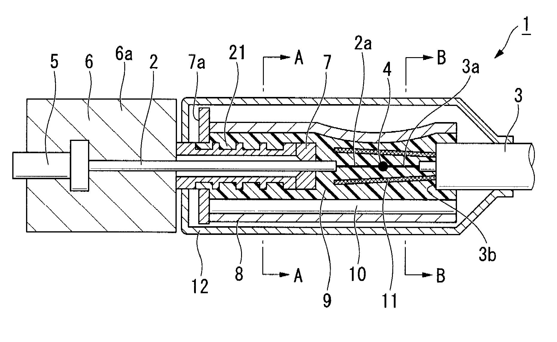
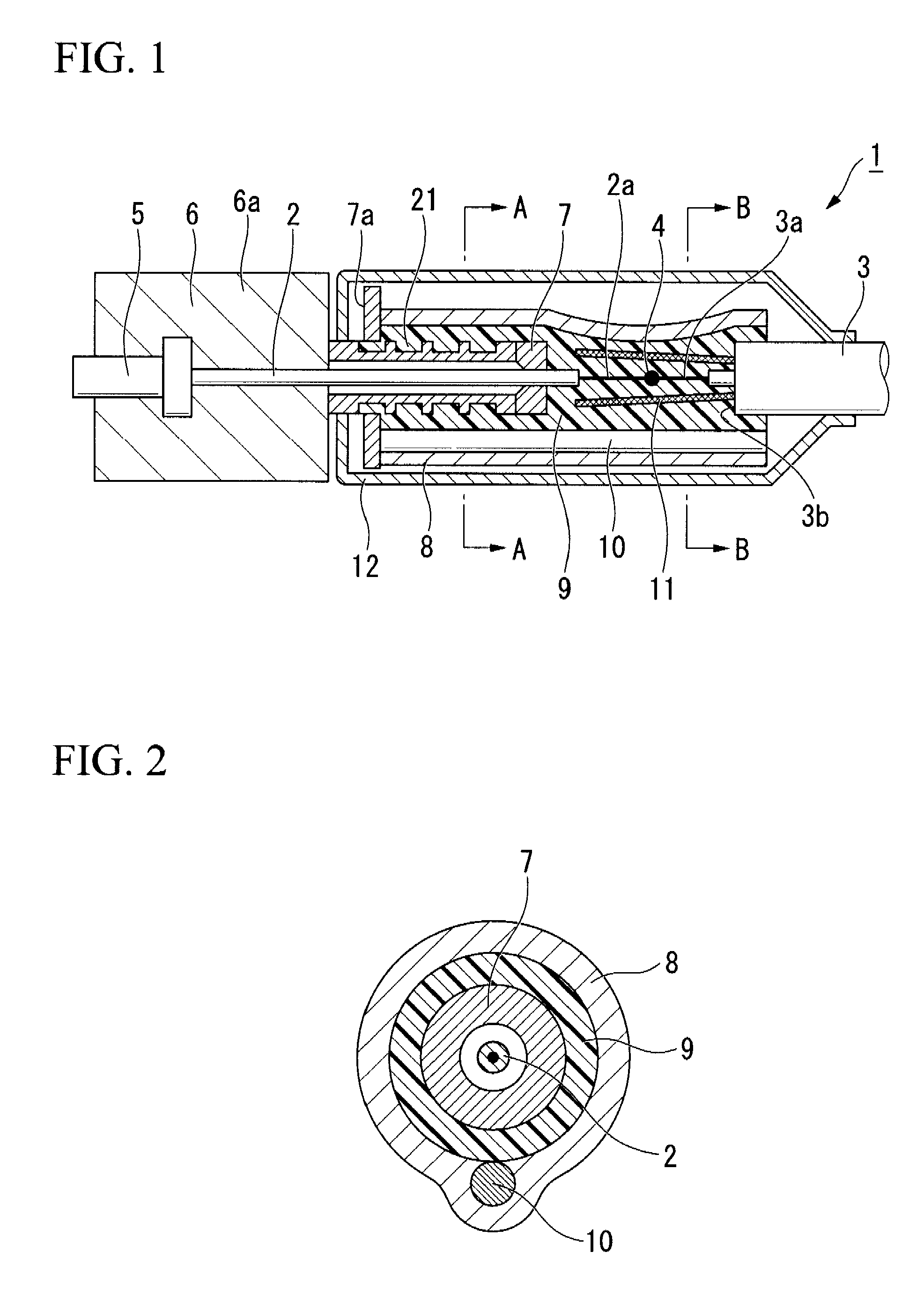
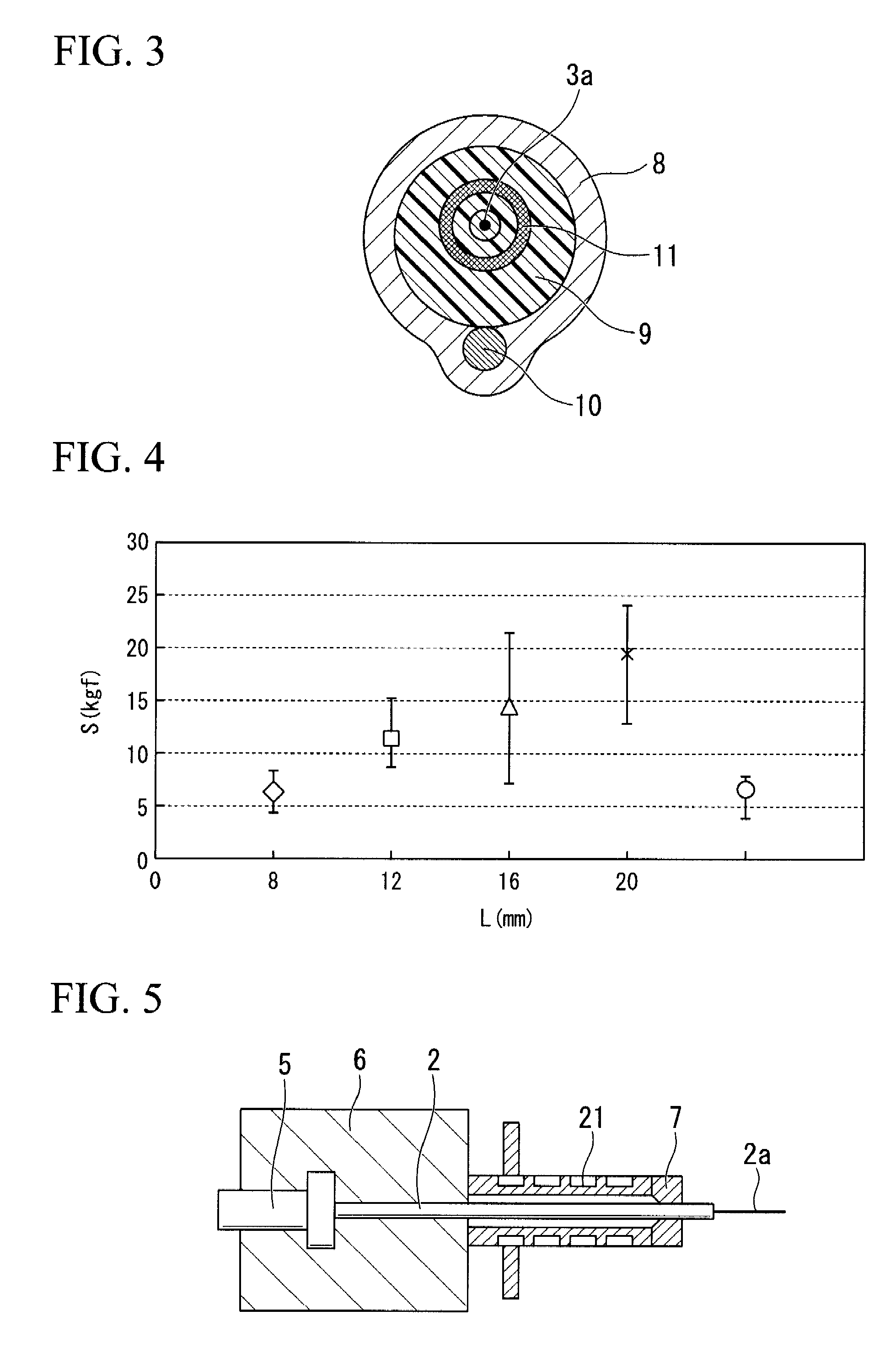
[0043]FIG. 1 is a cross sectional view illustrating an optical connector of an exemplary embodiment of the present invention. FIG. 2 is a cross-sectional view along the line A-A of FIG. 1. FIG. 3 is a cross sectional view along the line B-B of FIG. 1. In these figures, 1 denotes an optical connector connecting apparatus which includes a fused connection portion 4 in which a bare optical fiber 2a of an optical fiber 2 extending with a predetermined protruding length from an optical connector 6 and a bare optical fiber 3a of an optical fiber cord 3 are fused-connected.

[0044]Referring again to these figures, 5 denotes a ferrule into which the optical fiber 2 of the ...


PUM


Abstract

A method and apparatus of connecting an optical connector and an optical fiber cord are provided. The method includes providing the optical connector, a connector housing, a stop-ring structure, and an optical fiber; fusion-splicing a fiber end of the optical fiber of the optical connector and a fiber end of an optical fiber protruding from a cord end of an optical fiber cord; enclosing the cord end of the optical fiber cord and at least the stop-ring structure end. The sleeve includes an annular sleeve body, a hot melt resin layer applied to an inner surface of the sleeve body, a tensile-strength body embedded in the sleeve body or the hot melt resin layer. The sleeve is heated such that the hot melt resin layer is melted into molten resin which in turn fills the inner space of the sleeve and solidifies therein.

Description

CROSS-REFERENCE TO RELATED APPLICATIONS[0001]This application claims priority from Japanese Patent Application No. 2007-032617, filed on Feb. 13, 2007 in the Japanese Patent Office, the disclosures of which is incorporated herein by reference.BACKGROUND OF THE INVENTION[0002]1. Field of the Invention[0003]Apparatuses and methods consistent with the present invention relate to an optical connector connecting method and a structure produced by using the same, and more specifically to a method and a structure connecting an optical fiber of an optical connector and an optical fiber of an optical fiber cord.[0004]2. Description of the Related Art[0005]In the related art, as a fused connection structure in which an optical fiber of an optical connector and an optical fiber cord are connected by fusion, the structure (1) in which a bare optical fiber extended from a fine hole of a ferrule and an optical fiber are fused outside the ferrule and the thus-fused connection portion is covered wi...

Claims


Application Information

Patent Timeline
IPC IPC(8): G02B6/255
CPCG02B6/2551G02B6/3889G02B6/2558G02B6/3846
Inventor MIYAMOTO, MASAAKIIWASHITA, YOSHINORIKAWANISHI, NORIYUKITAKIZAWA, KAZUHIROKUBO, TOSHIKI
Owner THE FUJIKURA CABLE WORKS LTD
Why Eureka
Try Eureka