Epicyclic Gear System with Flexpins

a gear system and flexpin technology, applied in the field of gear systems, can solve the problems of excessive noise, friction and wear, and heavy stress on the inner pins

Active Publication Date: 2008-08-14
THE TIMKEN CO
View PDF13 Cites 51 Cited by
  • Summary
  • Abstract
  • Description
  • Claims
  • Application Information

AI Technical Summary

Problems solved by technology

Straddle carriers under heavy loads experience torsional wind up which causes one carrier wall to twist slightly ahead of the other carrier wall, thus skewing the pins and changing a mesh between the plane...

Method used


Image

  • Epicyclic Gear System with Flexpins
  • Epicyclic Gear System with Flexpins
  • Epicyclic Gear System with Flexpins

Examples


Embodiment Construction

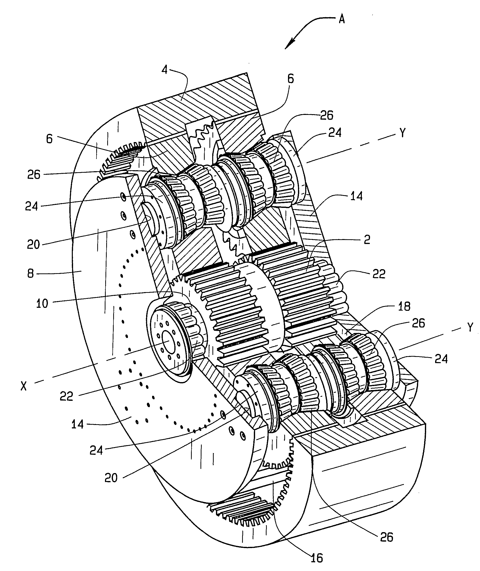
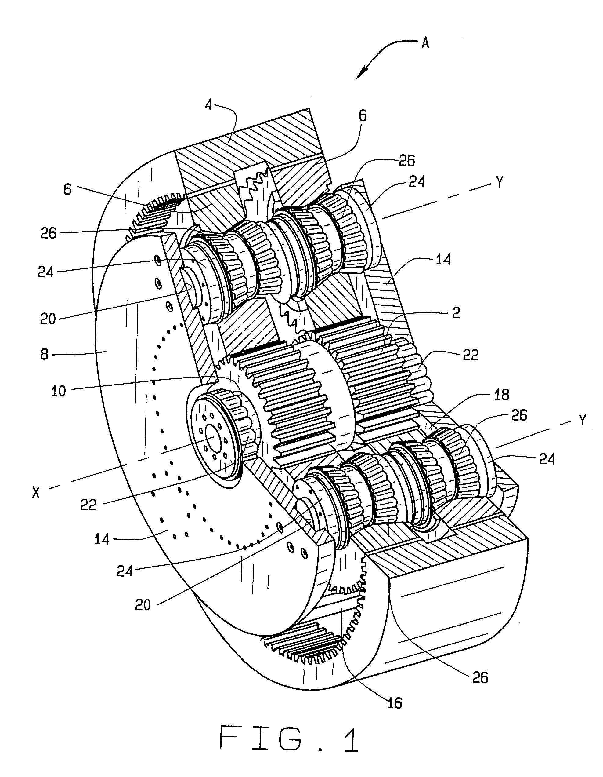
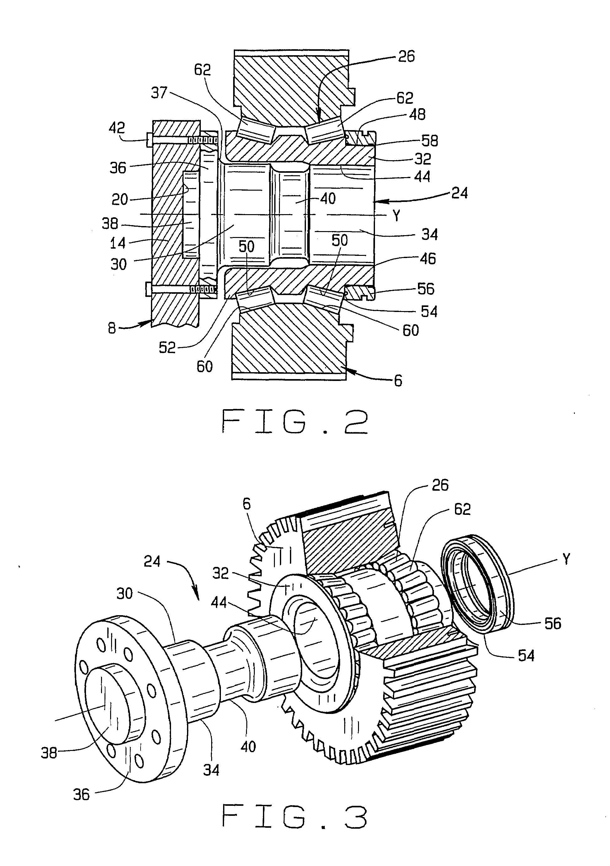
[0012]Referring now to the drawings, a epicyclic gear system A (FIG. 1) which is organized about a central axis X, includes a sun gear 2, a ring gear 4 surrounding the sun gear 2, planet gears 6 arranged in two arrays between the sun gear and ring gears 2 and 4 and engaged with both, and a carrier 8 on which the planet gears 6 revolve. The sun gear 2, the ring gear 4, and the carrier 8 share the central axis X, and if any one of them rotates, it rotates about the axis X. The planet gears 8 rotate about axes Y that are offset from the axis X, yet are generally parallel to the axis X.

[0013]The sun gear 2 has external teeth that may extend entirely across the gear 2 or they may be arranged in two rows, one for each of the arrays of planet gears 6. At its ends the sun gear 2 has spindles 10 that project axially into the carrier 8. The ring gear 4 has internal teeth that likewise may extend entirely across the gear or may be arranged in two rows. The planet gears 6 have external teeth th...


PUM


Abstract

An epicyclic gear system (A) includes a sun gear (2), a ring gear (4) located around the sun gear, planet gears (6) organized in two arrays between the sun and ring gears, and a carrier (8) having walls (14) located beyond the planet gears and flexpins (24) that project from the walls into the planet gears. Each flexpin includes an inner pin (30) provided with a flange 36 that is secured to the wall from which the inner pin projects, thus cantilevering the inner pin from the wall, and a sleeve (32) that is cantilevered from the opposite end of the inner pin and extends back over the inner pin, thus providing a double cantilever. Between the sleeve of the flexpin and the planet gear for that flexpin is a double row tapered roller bearing (26). The planet gears on the one array may be offset angularly with respect to the planet gears of the other array.

Description

RELATED APPLICATION[0001]This application derives and claims priority from U.S. provisional patent application 60 / 704,329 filed 1 Aug. 2005.TECHNICAL FIELD[0002]This invention relates in general to gearing and more particularly to epicyclic gear systems.BACKGROUND ART[0003]Epicyclic gear systems, often called planetary systems, have the capacity to transmit considerable power in confined spaces. Typical of such confined spaces are the nacelles of wind turbines. In a wind turbine a rotor driven by blades that catch the wind powers an electrical generator. But the rotor revolves slowly, while the generator must turn at a considerably higher velocity if it is to remain relatively small. To this end, a transmission exists between the rotor and the generator to increase the speed. Usually the transmission contains one or more epicyclic gear sets. The transmission must have a high power density.[0004]In its most basic form an epicyclic gear system has a sun gear and a ring gear located ar...

Claims


Application Information

Patent Timeline
IPC IPC(8): F16H1/28F16H1/48F16H57/08
CPCF03D11/02F16H1/2836Y10T74/19633Y02E10/722F16H57/082F03D15/00F03D15/10Y02E10/72
Inventor FOX, GERALD P.
Owner THE TIMKEN CO
Why Eureka
Try Eureka