
Rotatable helmet mount

a night vision device and mount technology, applied in the direction of optical elements, protective garments, instruments, etc., can solve the problems of user being placed in a potentially dangerous situation, undue and achieve the effect of reducing the strain on the neck of the user

Active Publication Date: 2005-10-25
NOROTOS
View PDF33 Cites 57 Cited by
  • Summary
  • Abstract
  • Description
  • Claims
  • Application Information

AI Technical Summary

Benefits of technology

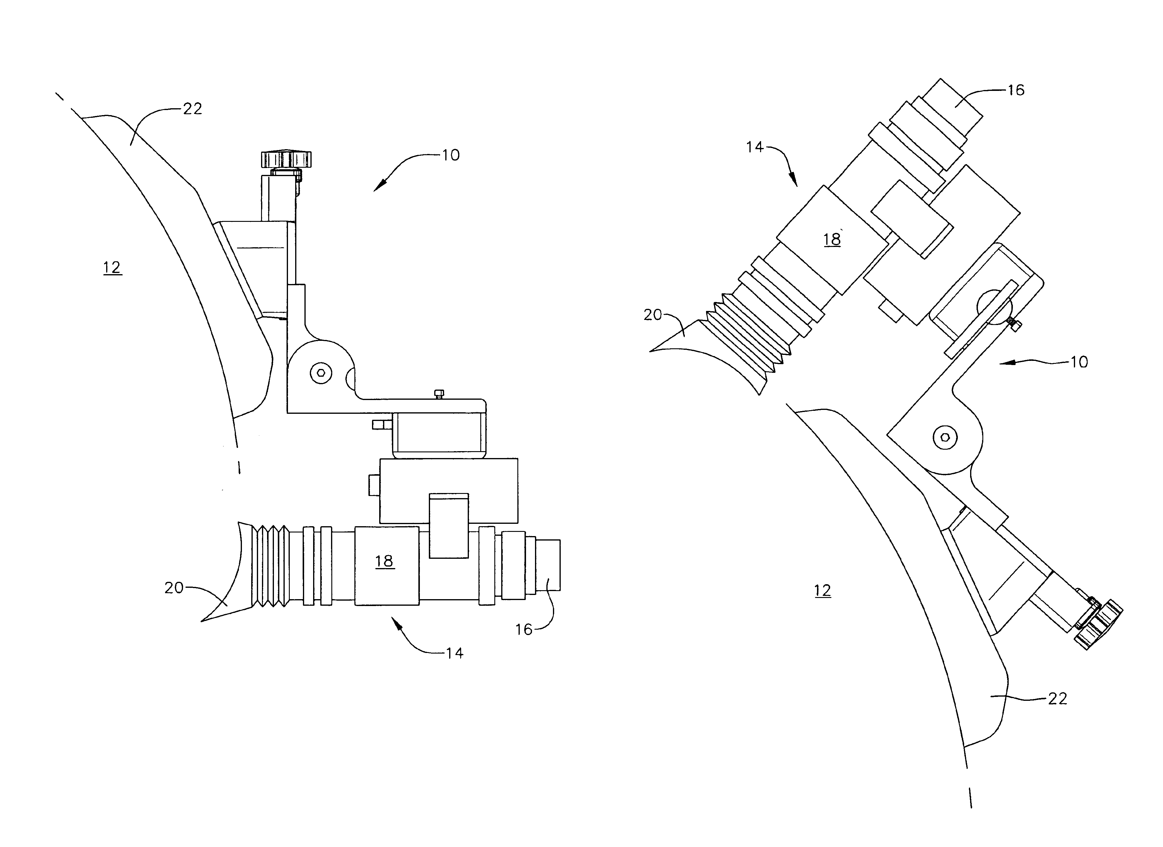
[0008]The present invention provides a different approach to a helmet mount for night vision devices. More particularly, the helmet mount according to the present invention is designed to rotate so that, in the stowed position, the center of gravity of the night vision device / helmet assembly is more directly over the center of the user's head, reducing strain on the user's neck. In addition, the rotatable helmet mount is designed so that the eyepieces which may emit a phosphor yellow / green light are flush with the helmet and the light is not particularly visible when the device is in a stowed position.

Problems solved by technology

This places the center of gravity of the night vision device / helmet mount assembly further forward than simply the helmet alone and may place an undue strain on the user's neck.
However, should the automatic shutdown assembly fail to operate for any reason, the user may be placed in a potentially dangerous situation.
These and other problems could exist with the flip-up helmet mounts for night vision devices disclosed in the prior art.
In addition, the rotatable helmet mount is designed so that the eyepieces which may emit a phosphor yellow / green light are flush with the helmet and the light is not particularly visible when the device is in a stowed position.

Method used


Image

  • Rotatable helmet mount
  • Rotatable helmet mount
  • Rotatable helmet mount

Examples


Embodiment Construction

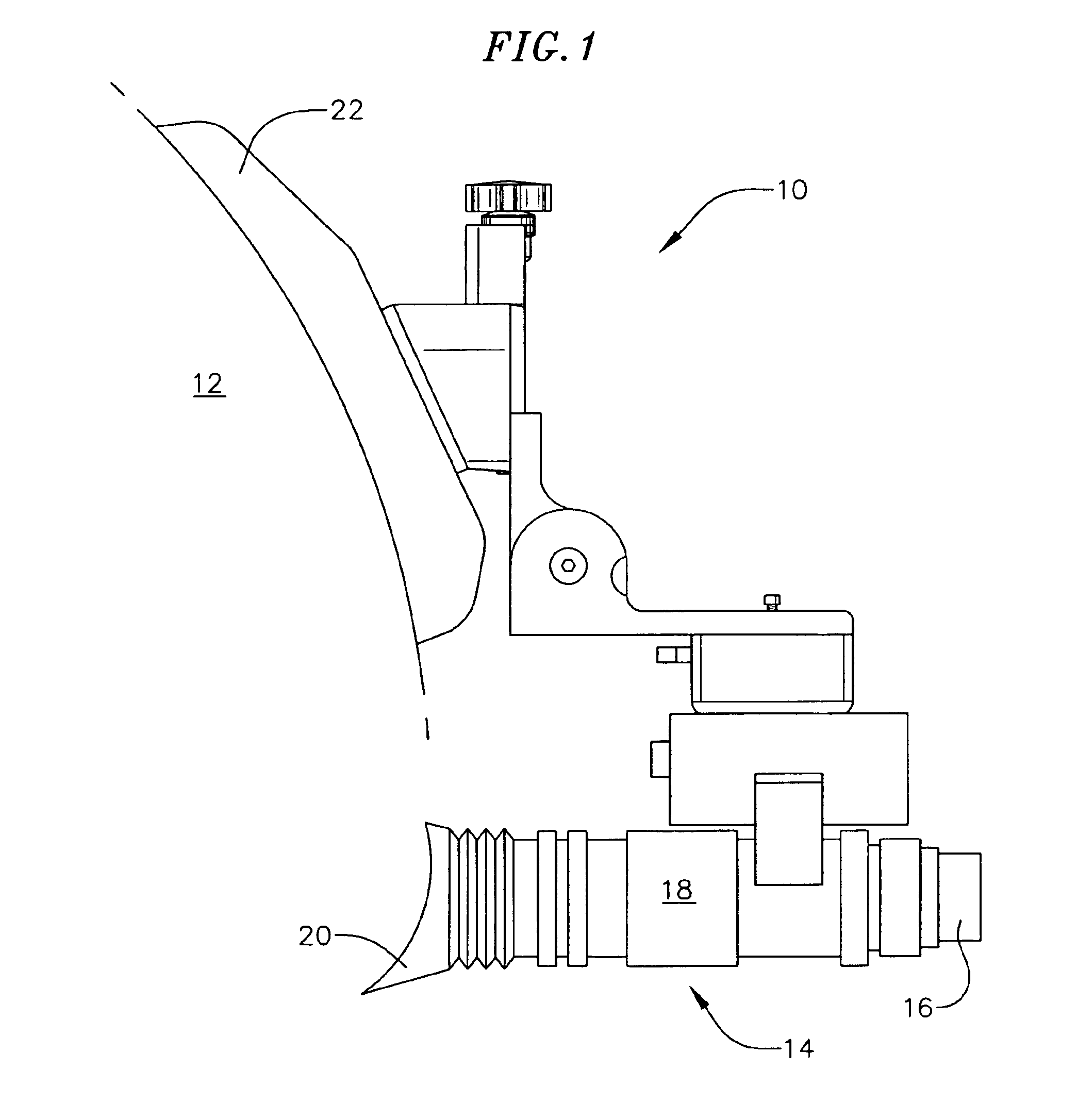
[0029]Referring now to FIG. 1, a presently preferred embodiment of a rotatable helmet mount 10 according to the present invention is shown. The rotatable helmet mount 10 is shown in use with a standard U.S. Army Kevlar composite helmet 12. A night vision device 14 is secured to the helmet 12 by use of the rotatable helmet mount 10. The night vision device 14 shown in FIG. 1 is a device that includes a single objective lens 16, a housing 18 and a pair of eye pieces 20. To use the night vision device 14, the operator places the device into the position depicted in FIG. 1 and looks into the eye pieces 20 to see an enhanced image representative of the low-level light from a night scene which has entered the objective lens.

[0030]The rotatable helmet mount 10 may be secured to the helmet 12 in any of the ways well known in the art. FIG. 1 shows the rotatable helmet mount secured to the helmet by means of a shroud plate 22. The shroud plate 22 is described in U.S. patent application Ser. N...


PUM


Abstract

A helmet mount for a night vision device is provided having means to attached to headgear, such as a helmet, wherein the mount is rotatable between a use position and a stowed position about an axis that is substantially parallel to the attachment means. In one embodiment, a position adjustment assembly comprises a rotary plate, a helmet block rotationally coupled to the rotary plate and a spring-biased ball and socket system located between the helmet bock and rotary plate. In another embodiment, a tilt adjustment assembly may include a gear system wherein rotation of a lever produces rotation of a night vision device relative to a user's eyes.

Description

CROSS-REFERENCE TO RELATED APPLICATION(S)[0001]This application claims the benefit of the filing date of U.S. Provisional Patent Application Ser. No. 60 / 460,538, filed Apr. 4, 2003 and entitled ROTATABLE HELMET MOUNT, the entire content of which is hereby expressly incorporated by reference.FIELD OF THE INVENTION[0002]This invention relates generally to mounting assemblies for night vision devices, and more particularly to a rotatable helmet mount for night vision devices that rotates a night vision device between a use position and a stowed position and preferably includes vertical adjustment, tilt adjustment, and focal adjustment. The invention may also include automatic shutdown assemblies.BACKGROUND OF THE INVENTION[0003]Night vision devices are commonly used by military personnel for conducting operations in low light or night conditions. The night vision devices utilized by the military typically include image intensifier tubes and associated optics that convert infrared and n...

Claims


Application Information

Patent Timeline
Patent Type & Authority Patents(United States)
IPC IPC(8): G02B23/00G02B23/12
CPCA42B3/04G02B23/125A42B1/24A42B3/044
Inventor PRENDERGAST, JONATHON R.
Owner NOROTOS
Learn More