

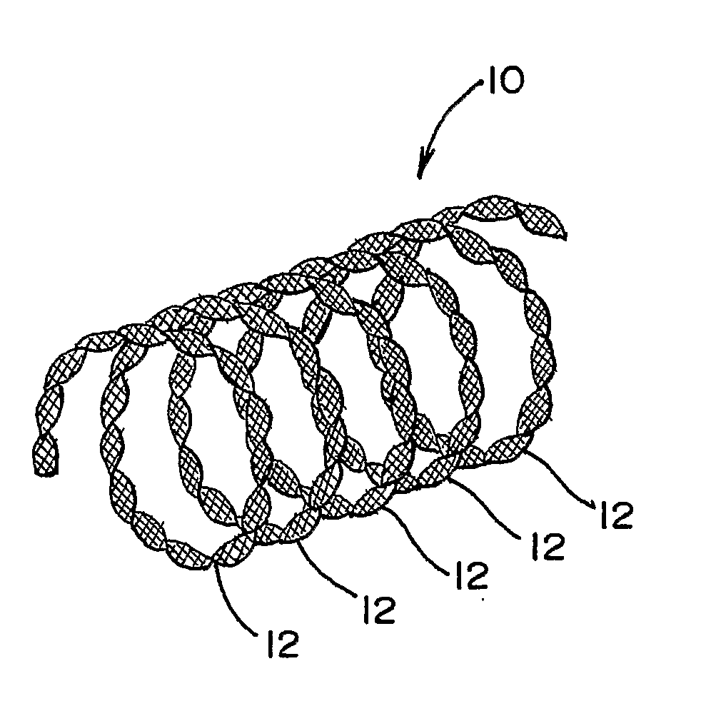
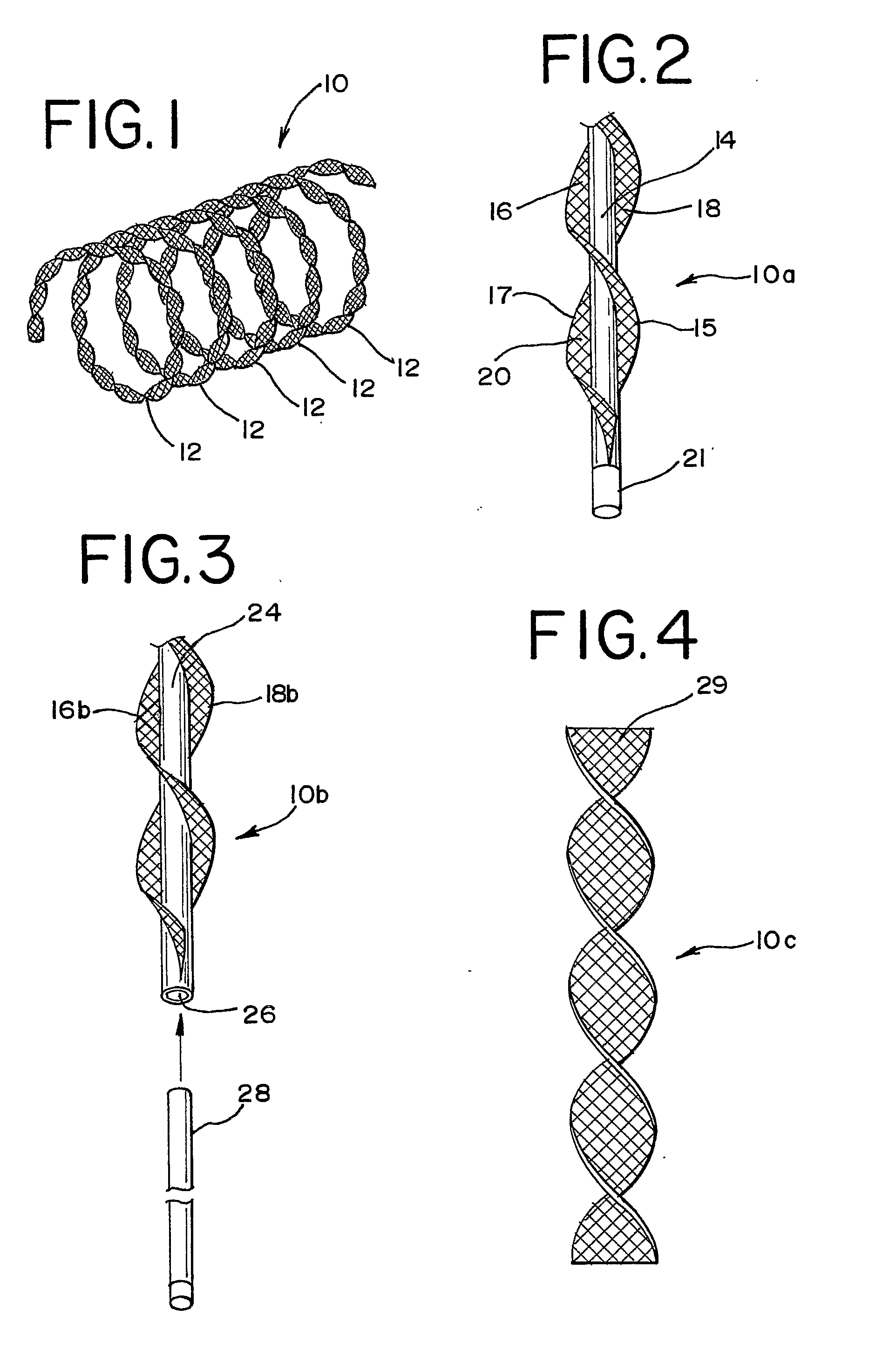
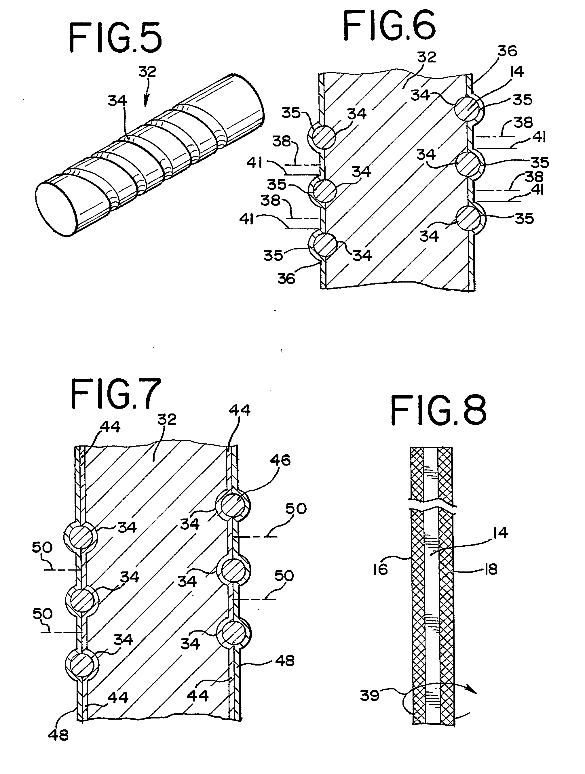
Vascular Occlusion Device With An Embolic Mesh Ribbon
a vascular occlusion device and embolic mesh technology, applied in the field of medical devices and methods, can solve the problems of aneurysms causing tissue surrounding the blood vessel to apply undesired pressure, wall to abnormally bulge or balloon outwardly, and pressure can be extremely problemati
- Summary
- Abstract
- Description
- Claims
- Application Information
AI Technical Summary
Benefits of technology
Problems solved by technology
Method used
Image

Examples
Embodiment Construction
[0029]As required, detailed embodiments of the present invention are disclosed herein; however, it is to be understood that the disclosed embodiments are merely exemplary of the invention, which may be embodied in various forms. Therefore, specific details disclosed herein are not to be interpreted as limiting, but merely as a basis for the claims and as a representative basis for teaching one skilled in the art to variously employ the present invention in virtually any appropriate manner.
[0030]The occlusion devices of the present invention are generally designed to be delivered to a preselected site within a vessel of a patient by using standard deployment systems, such as TRUFILL® DCS ORBIT™ (Cordis Corporation) hydraulic detachable coils deployment systems, other mechanical, electrolytic or thermal systems or the like, or any other deployment systems or techniques that may be developed in the future. For convenience and simplicity, the following description of the present inventi...
PUM
 Abstract
Description
Claims
Application Information