Dynamic spinal deformity correction

a spinal deformity and dynamic technology, applied in the field of dynamic stabilization techniques, can solve the problems of significant invasiveness of the transverse process, requiring the application of bone graphs, and requiring permanent fixation of supporting clamps, and achieve the effect of full flexion and extension

Inactive Publication Date: 2008-08-14
REDUCTION TECH
View PDF53 Cites 188 Cited by
  • Summary
  • Abstract
  • Description
  • Claims
  • Application Information

AI Technical Summary

Benefits of technology

[0019]The present invention is directed to a system for treating spinal deformities comprising a plurality of retaining clamps fixed to a plurality of vertebra and at least one elastic or super elastic rod caused to pass through openings in said plurality of retaining clamps. The at least one elastic or super elastic rod being slidable within each of the plurality of retaining clamps along the axis of the spine, the flexibility of said at least one elastic or super elastic rod and its movement in said plurality of retaining clamps being sufficient to enable the spine to retain full flexion and extension in both its coronal and sagittal planes.

Problems solved by technology

If this treatment proves unsuccessful, surgery is oftentimes resorted to.
Although spinal fusion can oftentimes largely correct a spinal deformity, such procedure is not without serious drawbacks.
Spinal fusion can result in complications as the patient advances into adult life.
The surgery requiring the application of bone graphs and permanent fixation of supporting clamps to the transverse process is significantly invasive.
In addition, although fusion may result in strengthening a portion of the spine, it is also been linked to more rapid degeneration and collapse of spinal motion segments that are adjacent to the portion of the spine being fused, reducing or eliminating the ability of such spinal joints to move in a more normal relation to one another.
Also, fusion has oftentimes failed to provide pain relief.
While there is a good deal of prior art dealing with dynamic stabilization using elastic members captured by pedicle screws, none of these devices are capable of reducing deformities over time.
The disclosed structure does not allow axial motion of the sliding of rods.
The disclosed construction does not actively compensate for creep or tissue relaxation and does not adequately treat deformities as it is taught that at least some of the rods are locked thus fixing the deformity.
The system is not adequate in treating deformities as locking one or two rods with screws fixes the deformity and does not allow for correction.
U.S. Pat. No. 6,989,011 teaches a construction that limits spinal motion noting further that the corrective rods are locked in place and are therefore not capable of reducing the deformity.
In the '524 publication, an outer sleeve is disclosed which is locked in the pedicle or bone screws and will not allow for deformity reduction.
U.S. Published Application No. 2006 / 0229612 teaches a system that allows for axial motion or “springs,” but there is no disclosed mechanism to retain the “springs” in extreme spinal flexion.
The device disclosed in this publication will generally stabilize a normal spine quite well but is not adapted to reduce spinal deformities.
There is no disclosure of axial motion in the system noting that fixed initial lengths of the rods do not allow for continued correction of the deformity.

Method used


Image

  • Dynamic spinal deformity correction
  • Dynamic spinal deformity correction
  • Dynamic spinal deformity correction

Examples


Embodiment Construction

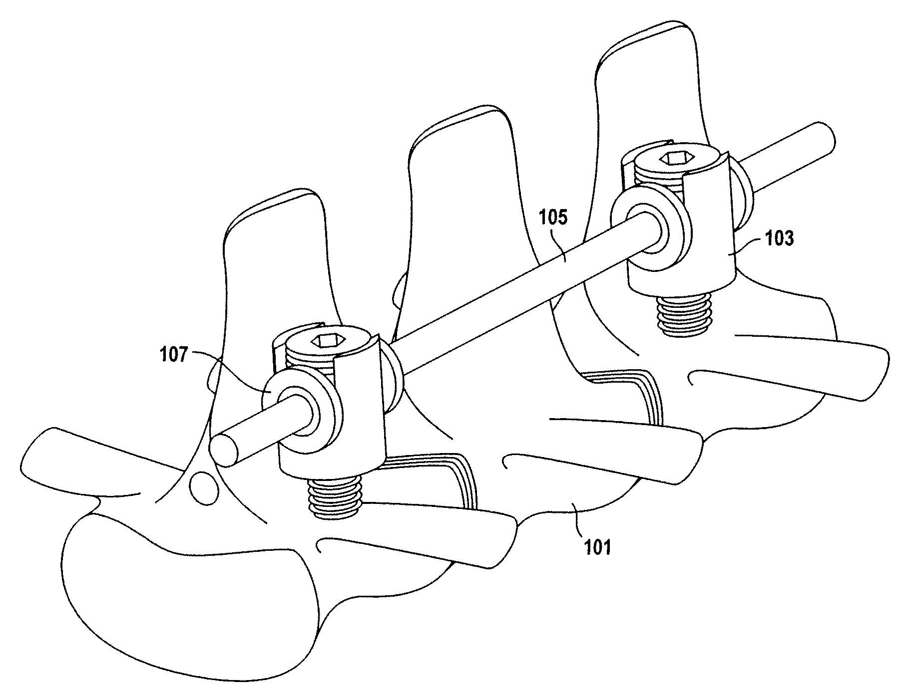
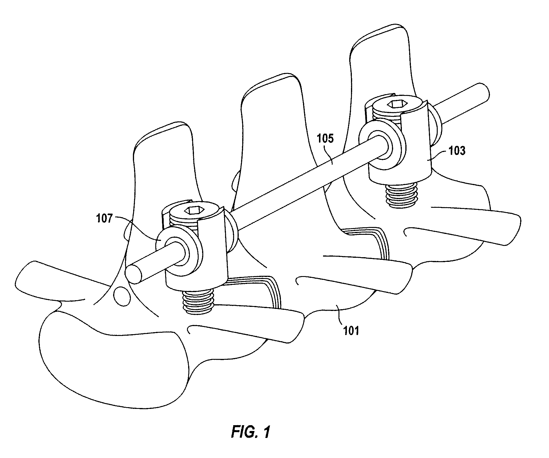
[0028]Turning first to FIG. 1, spine 101 is shown instrumented with pedicle screws 103. Installed in each pedicle screw is rod adapter 107. Elastic or super elastic corrective rods 105 are caused to pass through each rod adapter noting that the rod adapter freely allows axial translation of the corrective rods. The goal of this device is to transfer forces from the corrective rods to the vertebrae and spine through existing and available fixation devices while providing full flexion and extension in the spine's coronal and saggital planes, thus minimizing if not completely eliminating the possibility of spinal fusion. As will be more readily apparent in the discussion which follows, the present invention adapts to existing and available fixation systems using elastic or super elastic correction rods to slowly correct deformities without fusion while retaining full range of motion and full flexion and extension in the spine's coronal and saggital planes.

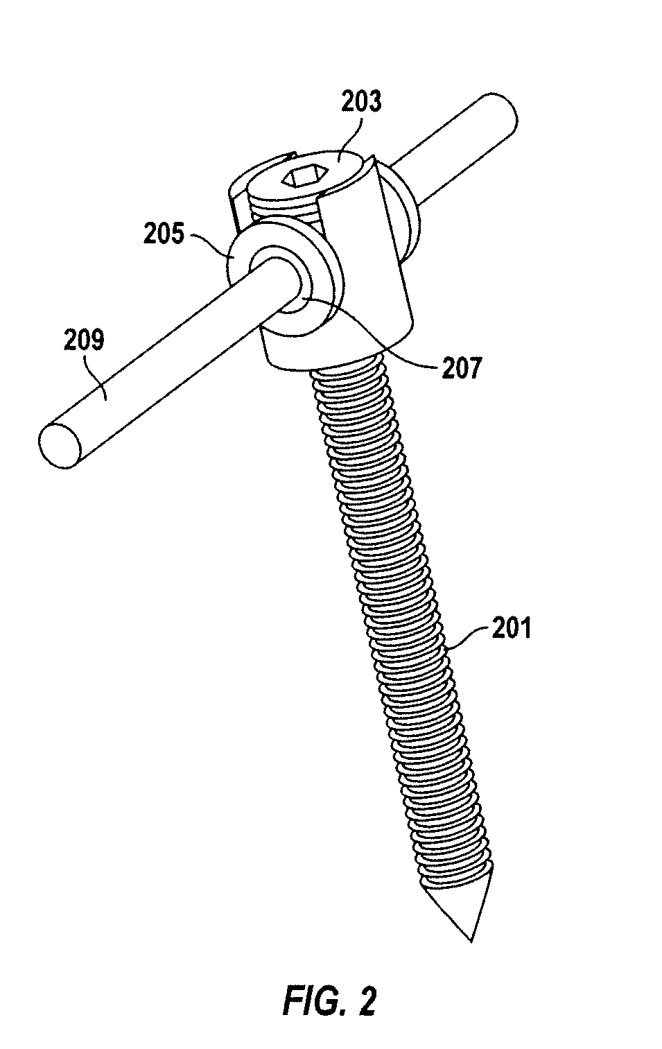
[0029]Rod adapter 107 can be s...


PUM


Abstract

A system for treating spinal deformities. A plurality of retaining clamps are fixed to a plurality of vertebrae and at least one elastic or super elastic rod is caused to pass through openings in the plurality of retaining clamps, the at least one elastic or super elastic rod being slidable within each of the plurality of retaining clamps along the axis of the spine to enable the spine to retain full flexion and extension in both its coronal and saggital planes.

Description

RELATED APPLICATION DATA[0001]This nonprovisional utility patent application claims priority to provisional patent application No. 60 / 888,831, filed on Feb. 8, 2007.TECHNICAL FIELD[0002]The present invention involves the use of dynamic stabilization techniques employing elastic or super elastic members captured by pedicle screws or like retaining clamps to reduce spinal deformities, such as scoliosis, over time. The present invention can be employed without resorting to spinal fusion or other immobilization techniques.BACKGROUND OF THE INVENTION[0003]Spinal deformities are quite common generally affecting more girls than boys and manifesting itself during the teen years when significant growth is experienced. Scoliosis, the most common form of deformity, generally combines horizontal torsion and flexion in the frontal plane and develops in three spatial dimensions. As noted, the disease generally begins with the growth phase as it is hypothesized that this is probably due to the rot...

Claims


Application Information

Patent Timeline
Patent Type & Authority Applications(United States)
IPC IPC(8): A61B17/58
CPCA61B17/7008A61B17/702A61B17/7046A61B17/7041A61B17/7049A61B17/7031
Inventor THOMPSON, MATTHEW
Owner REDUCTION TECH
Why Eureka
Try Eureka