Ankle prosthesis for the arthrodesis of the calcaneum

a technology of calcaneum and prosthesis, applied in the field of prosthesis, can solve the problems of delay in implantation of articular prosthesis, ineffective blockage of articulation by assembly, and patient's pain, and achieve the effect of relieving pain

Active Publication Date: 2008-08-14
SMITH & NEPHEW INC +2
View PDF33 Cites 35 Cited by
  • Summary
  • Abstract
  • Description
  • Claims
  • Application Information

AI Technical Summary

Benefits of technology

[0031]This method makes it possible, in a single surgical intervention, to implant a prosthetic ankle assembly of the kind defined above, in order to permit arthrodesis of the calcaneus and astragalus and, at the same time, arthroplasty between the astragalus and the tibia of a patient. Arthrodesis refers to a surgical fixation of a joint, ultimately resulting in bone fusion. Basically, the procedure is artificially induced ankylosis performed to relieve pain or provide support in a diseased or injured joint.

Problems solved by technology

This results in a considerable loss of mobility for the patient, since the ankle is totally blocked.
However, the two articulations then have to be treated in two stages: the arthrodesis of the calcaneus and astragalus requires a consolidation period of at least six months, which delays the implantation of the articular prosthesis between the astragalus and the tibia.
However, the assembly does not effectively block the articulation between the calcaneus and the astragalus, since relative movements around and / or along the rod remain possible and, in practice, appear quickly.
Thus, the posterior foot of this prosthetic assembly provides a stable means of bearing on the calcaneus, but, even in the form of a screw inserted into cement, this foot does not totally block the articulation between the astragalus and the calcaneus in an effective manner.
Hence, this rod does not provide any effective blocking of the articulation between the calcaneus and the astragalus so that, in order to limit the relative movements between these two bones, additional screws are fitted between the astragalar plate and the astragalocalcanean rod, in order to stabilize the position of the latter.

Method used


Image

  • Ankle prosthesis for the arthrodesis of the calcaneum
  • Ankle prosthesis for the arthrodesis of the calcaneum
  • Ankle prosthesis for the arthrodesis of the calcaneum

Examples


Embodiment Construction

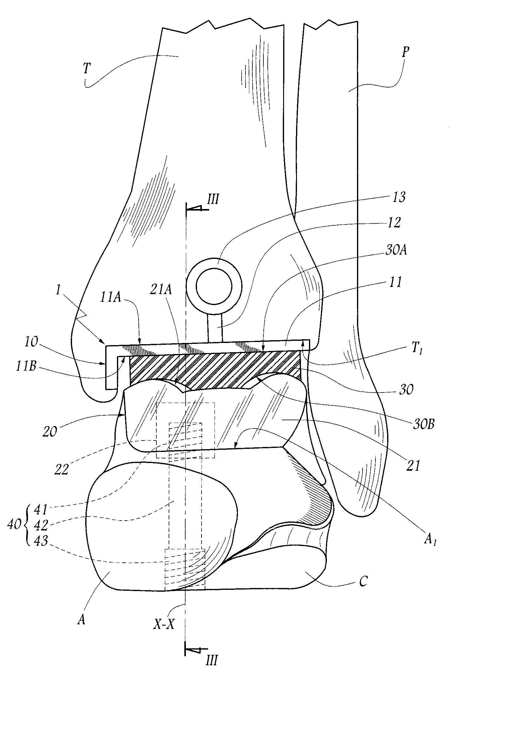
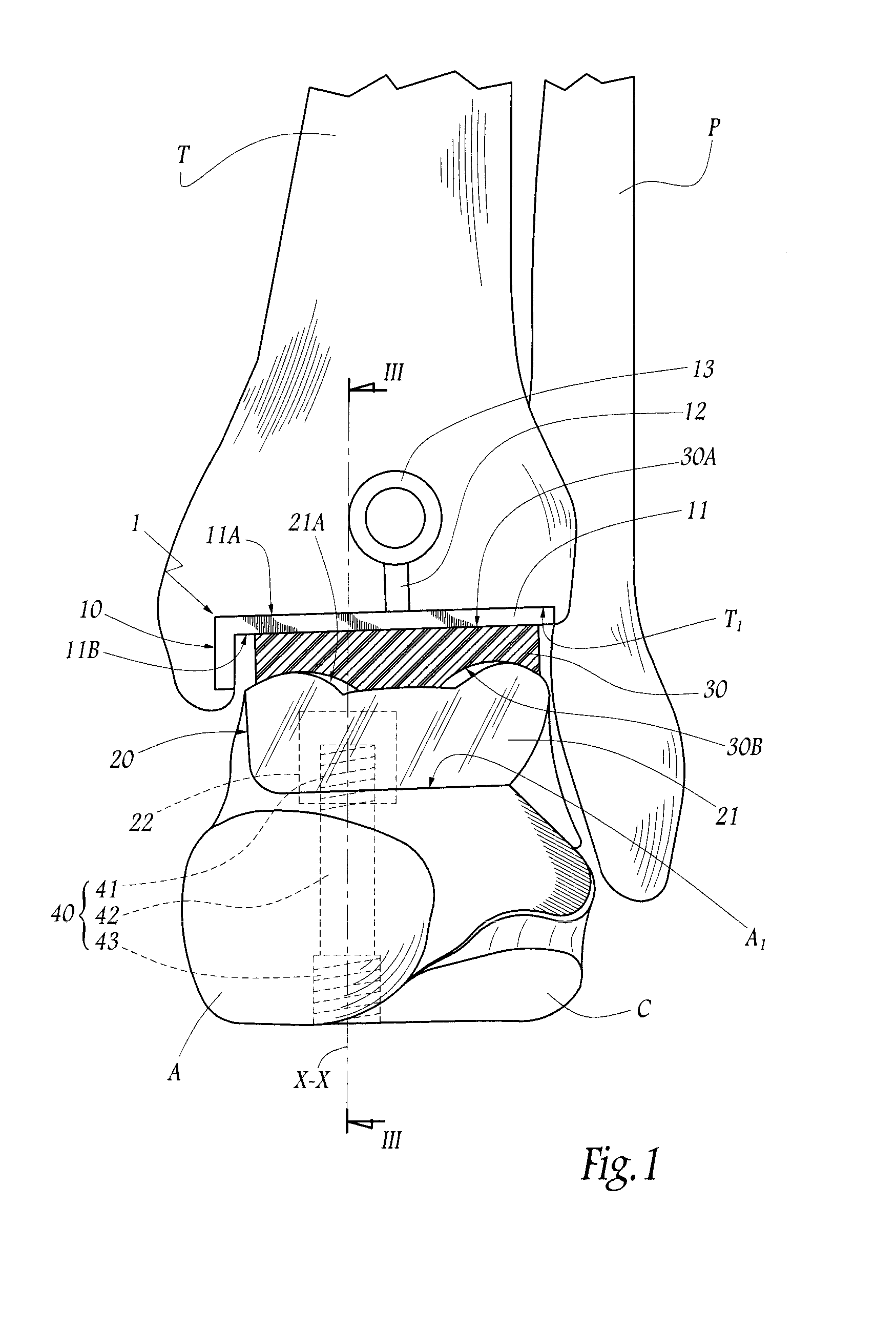
[0041]FIG. 1 shows schematically the lower ends of a tibia T and of a peroneal bone P or fibula of a human being, and also the corresponding astragalus A and calcaneus C, thereby illustrating the constituent bones of the left ankle of a patient. FIG. 1 also shows a prosthetic ankle assembly 1 comprising four separate components implanted in the ankle of the patient, namely a tibial component 10, an astragalar component 20, a prosthetic bearing 30, interposed between the tibial and astragalar components, and an astragalocalcanean rod 40. In FIG. 1, only the bearing 30 is shown in frontal section, whereas the broken lines are used to symbolize the contours of the components concealed by bone substance.

[0042]For convenience, the description that follows relates to the bones of the ankle in their anatomical position, that is to say the terms “posterior” or “rear”, “anterior” or “front”, “upper”, “lower”, etc., are to be understood in relation to the ankle of the patient when standing up...


PUM


Abstract

A prosthetic ankle assembly including an astragalar component with an upper articular surface that forms part of an ankle joint prosthesis and a lower surface with a shape adapted to engage an upper face of an astragalus. An astragalocalcanean rod is positioned in an astragalocalcanean channel extending from the lower face of the calcaneus to the upper surface of the astragalus. A first end of the astragalocalcanean rod is engage with the lower surface of the astragalar component and a second end of the astragalocalcanean rod is engaged with a lower region of the calcaneus. A distance between the second end of the astragalocalcanean rod is adjustable relative to the lower surface of the astragalar component to adjustably compress the calcaneus against the astragalus.

Description

CROSS-REFERENCE TO RELATED APPLICATIONS[0001]The present application claims priority to prior French Application No. 06 09001, filed Oct. 13, 2006, entitled ANKLE PROSTHESIS FOR THE ARTHRODESIS OF THE CALCANEUM.FIELD OF THE INVENTION[0002]The present invention relates to a prosthetic ankle assembly and to a surgical method for implanting such an assembly, and in particular, to the treatment of an ankle in which the articulation between the astragalus and the calcaneus are damaged.BACKGROUND OF THE INVENTION[0003]One possible treatment involves fusing the three bones represented by the calcaneus, astragalus and tibia, as is proposed in US-A-2005 / 0107791. A long compression screw internally connects the tibia and the calcaneus by passing through the astragalus, in such a way as to block these three bones relative to one another. This results in a considerable loss of mobility for the patient, since the ankle is totally blocked.[0004]Another possible treatment involves fusing the calca...

Claims


Application Information

Patent Timeline
Patent Type & Authority Applications(United States)
IPC IPC(8): A61F2/64
CPCA61F2/4202A61F2002/30405A61F2002/30426A61F2002/3055A61F2002/30604A61F2002/30672A61F2002/4217A61F2002/30884A61F2002/4205A61F2002/4207A61F2220/0025A61F2002/4212A61F2002/30851
Inventor FERRARI, IRENEWEBER, MICHAEL
Owner SMITH & NEPHEW INC
Why Eureka
Try Eureka