Cooling Fluid Flow Regulation Distribution System and Method

a distribution system and flow regulation technology, applied in the direction of domestic cooling devices, lighting and heating devices, instruments, etc., can solve the problems of not being economically practical in commercial development of spring-based flow regulators, unable to meet the requirements of flow rate and flow range tolerances, and the limitation of air as a cooling medium

Active Publication Date: 2008-08-21
VERTIV CORP
View PDF23 Cites 10 Cited by
  • Summary
  • Abstract
  • Description
  • Claims
  • Application Information

AI Technical Summary

Benefits of technology

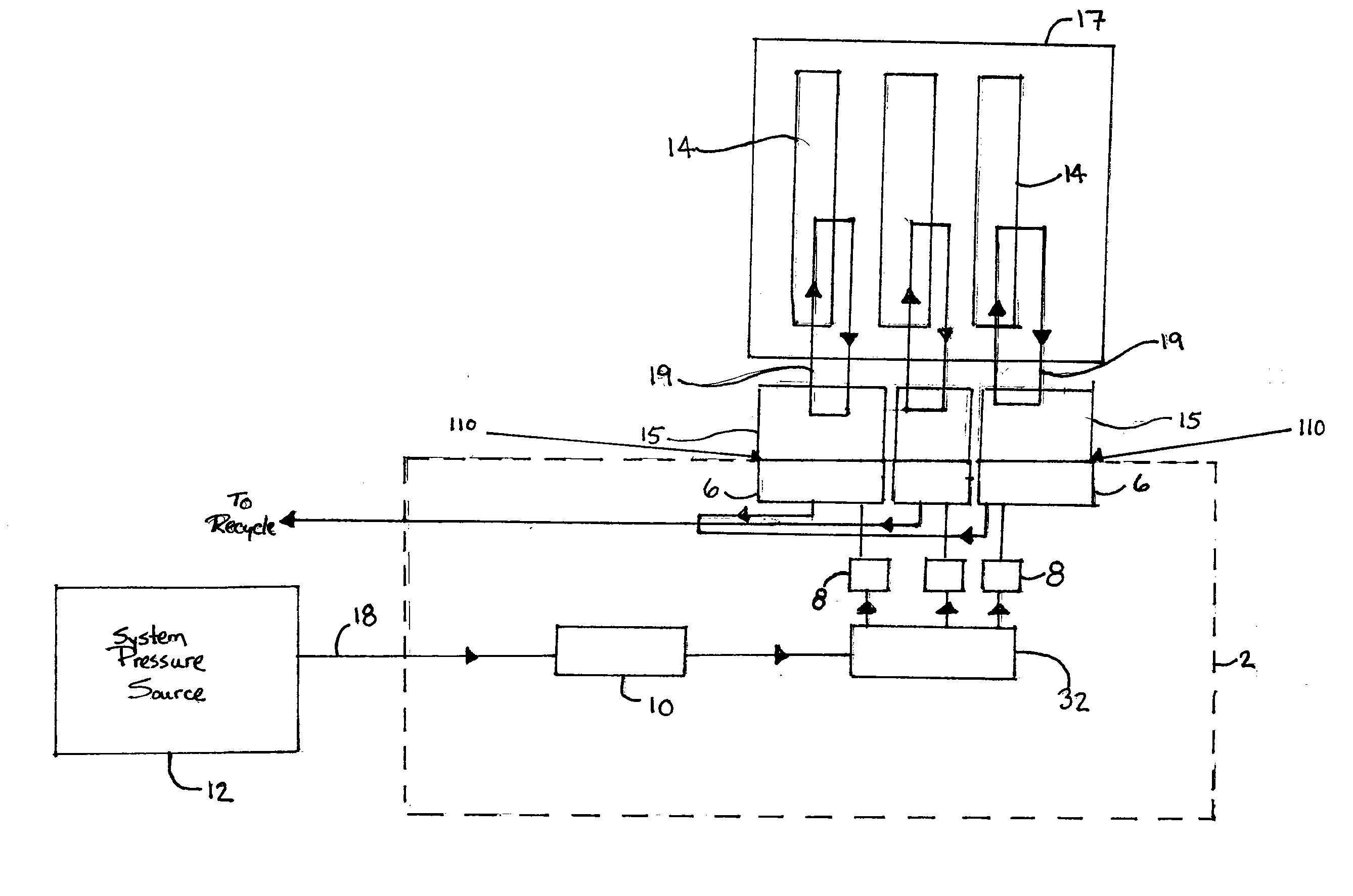
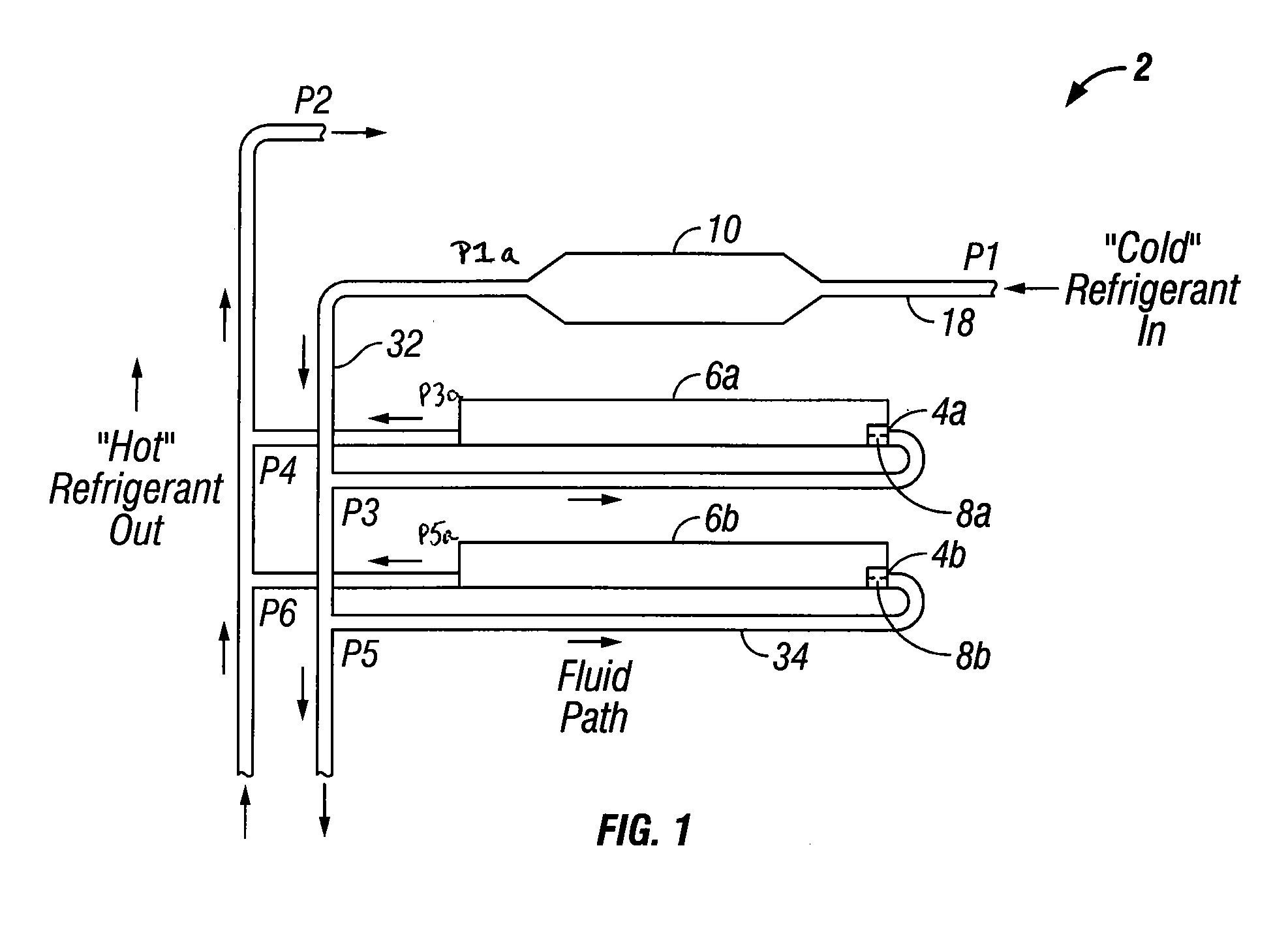
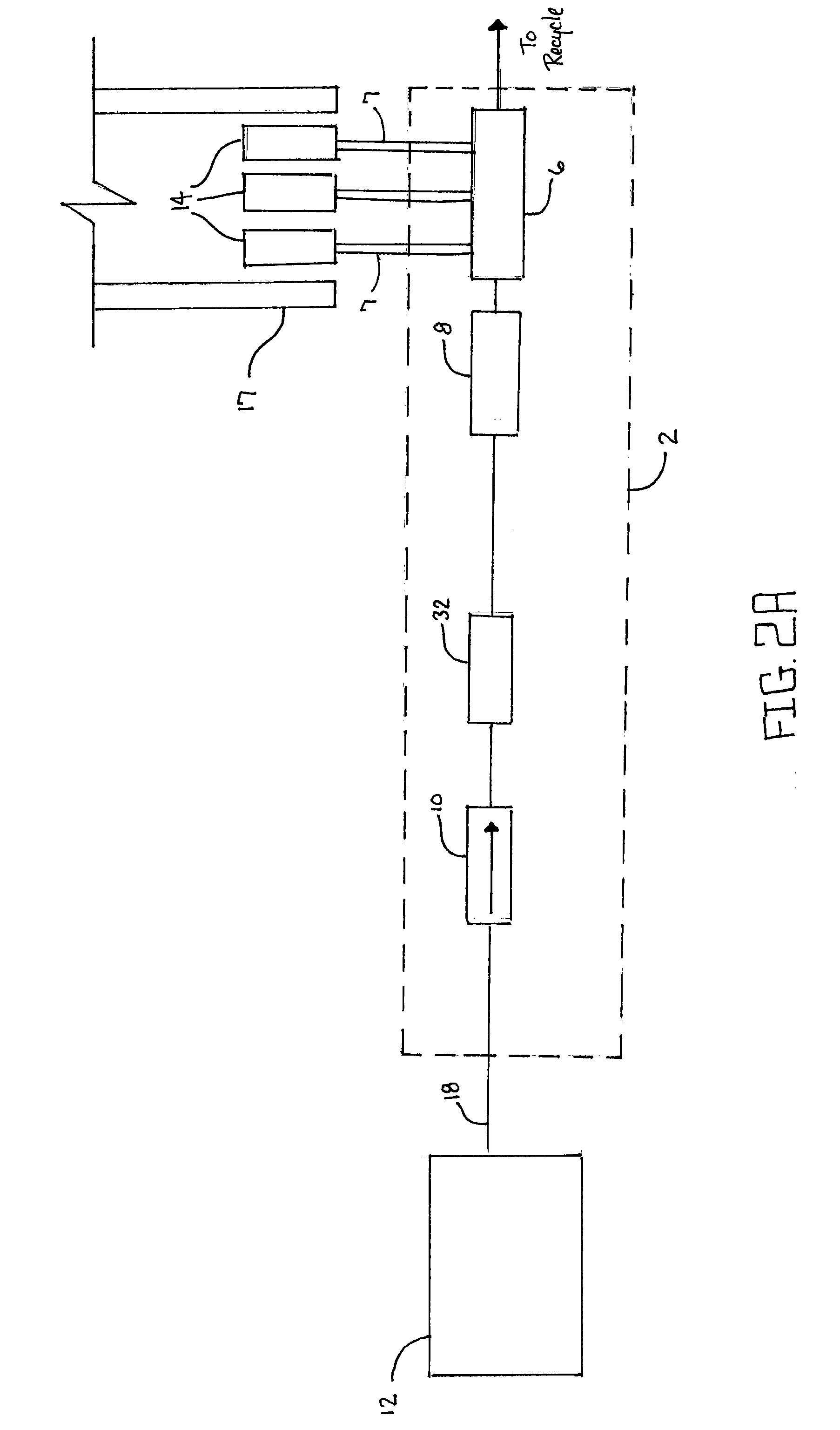
[0009]In accordance with an aspect of the present disclosure, systems are provided for regulating and distributing cooling fluid flow through a plurality of cold plates coupled to one or more electronic devices, wherein the systems comprise a flow regulator fluidicly coupled to a system pressure source; a distribution header fluidicly coupled to the flow regulator; a plurality of cooling fluid lines fluidicly coupled to the distribution header; at least two orifices, each of the orifices being coupled to a cooling fluid line downstream of the flow regulator and the distribution header; and a plurality of cold plates coupled to the plurality of fluid lines downstream of the orifices.
[

Problems solved by technology

With the ongoing shrinkage of electronic devices, the use of air as a cooling medium has reached a limitation on how much heat can be reasonably removed with a reasonably attainable air stream.
However, considering the typical nature, size and number of cold plates needed for the cooling of many electronic devices, there are no commercially available s

Method used


Image

  • Cooling Fluid Flow Regulation Distribution System and Method
  • Cooling Fluid Flow Regulation Distribution System and Method
  • Cooling Fluid Flow Regulation Distribution System and Method

Examples


Embodiment Construction

[0020]The Figures described above and the written description of specific structures and processes below are not presented to limit the scope of what Applicants have invented or the scope of protection for those inventions. Rather, the Figures and written description are provided to teach any person skilled in the art to make and use the inventions for which patent protection is sought. Those skilled in the art will appreciate that not all features of a commercial implementation of the inventions are described or shown for the sake of clarity and understanding. Persons of skill in this art also appreciate that the development of an actual commercial embodiment incorporating aspects of the present inventions will require numerous implementation-specific decisions to achieve the developer's ultimate goal for the commercial embodiment. Such implementation-specific decisions may include, and likely are not limited to, compliance with system-related, business-related, government-related ...


PUM


Abstract

The disclosure provides systems and methods for regulating and distributing cooling fluid through a plurality of heat sinks, such as cold plates, using a flow regulator, which sets the total flow rate, in combination with one or more individual orifices that allow further flow distribution as required by individual cold plates, despite flow variations upstream of the orifices. An orifice can be coupled to an orifice holder, which includes a body to support the orifice, and which may be coupled (directly or indirectly) to an inlet of the cold plate. Alternative manners of coupling orifices in the fluid flow besides an orifice holder can be employed. Generally, the flow regulator(s) is coupled with a plurality of orifices and conduits through which the cooling fluid flows. Related system components can be assembled as a module for installation into a cooling system that includes other system components such as a pump, compressor or other pressure sources for the cooling fluid.

Description

CROSS REFERENCE TO RELATED APPLICATIONS[0001]The present application claims priority to U.S. Provisional Patent Application Ser. No. 60 / 890,555, filed Feb. 19, 2007, the contents of which are incorporated herein by reference in its entirety.STATEMENT REGARDING FEDERALLY SPONSORED RESEARCH OR DEVELOPMENT[0002]Not applicable.REFERENCE TO APPENDIX[0003]Not applicable.BACKGROUND OF THE INVENTION[0004]The present invention relates generally to cooling fluid flow and control, and more particularly, to methods and systems for ensuring evenly distributed cooling fluid flow to a group of electrical device cooling components.[0005]Many industries use various types of electronic devices, such as computer servers and other electronic devices having electronic processors and sensors that generate heat during use. The electronic devices are frequently attached to racks capable of supporting the electronic devices and require the continuous removal of heat for proper operation. With the ongoing sh...

Claims


Application Information

Patent Timeline
IPC IPC(8): F28D15/00H05K7/20
CPCH05K7/20281H05K7/20645H05K7/20F28D15/00F28F9/02G06F1/20
Inventor SPEARING, IAN
Owner VERTIV CORP
Why Eureka
Try Eureka