Brushless motor and pump mounted with brushless motor

Inactive Publication Date: 2008-08-21
NIDEC CORP
View PDF20 Cites 16 Cited by
  • Summary
  • Abstract
  • Description
  • Claims
  • Application Information

AI Technical Summary

Benefits of technology

[0012]The brushless motor of the present invention can enhance the strength of the inner cover by arranging a plurality of radial ribs extending in the radial direction and arranged radially and a circumferential rib forming a circular ring shape or a circular arc shape with the center axis as the center on

Problems solved by technology

1) The number of components increases by using the lid member 3e, which is a separate member, for reinforcement of the inner cover 3b, and thus the unit cost of the pump increases.
2) The bottom portion 3b3 may not be able to withstand the water pressure since the strength of the bottom portion 3b3 of the inner cover 3b at the portion where the Hall element 4 is arranged is low. As a

Method used


Image

  • Brushless motor and pump mounted with brushless motor
  • Brushless motor and pump mounted with brushless motor
  • Brushless motor and pump mounted with brushless motor

Examples


Example

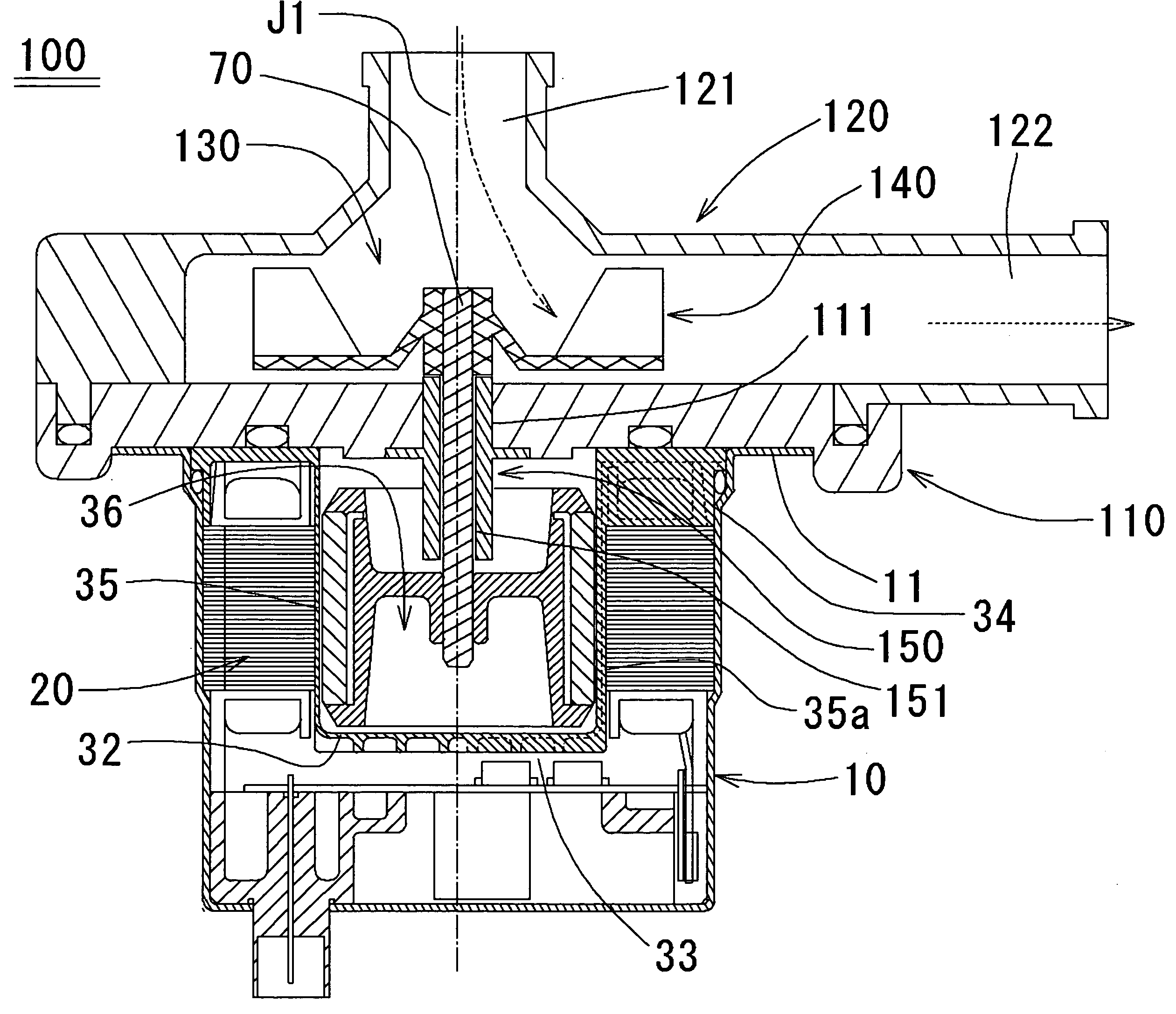
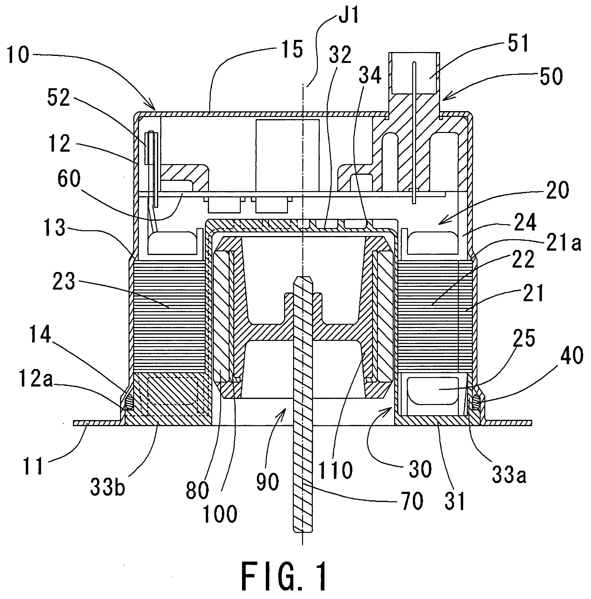
[0021]One aspect of an embodiment of a motor according to the present invention will now be described with reference to FIG. 1. FIG. 1 is a frame format cross sectional view of the motor taken along the axial direction. With regards to the terms upper side and the lower side herein, the bottom portion side of the inner cover is considered the upper side and the opening side is considered the lower side with respect to the center axis J1. The upper side and the lower side described herein does not necessary match the direction of gravitational force. The center axis J1 is arranged so as to be coaxial with the rotation axis, which is the center of rotation of the rotating body 90.

[0022]With reference to FIG. 1, an outer cover 10 of bottomed cylindrical shape having a predetermined center axis J1 as the center is formed by plastic forming such as press working the steel plate. The outer cover 10 is opened on the lower side in the direction (hereinafter referred to simply as axial direc...


PUM


Abstract

A bottom portion side rib and a flange portion side rib are respectively formed on the bottom portion and the flange portion of the inner cover. The bottom portion side rib includes a plurality of bottom portion side radial ribs and a plurality of bottom portion side circular ring shaped ribs connecting the plurality of bottom portion side radial ribs. The flange portion side rib includes a plurality of flange portion side radial ribs and a flange portion side circular ring shaped rib connecting the plurality of flange portion side radial ribs.

Description

BACKGROUND OF THE INVENTION[0001]1. Technical Fields[0002]The present invention relates to a brushless motor in which an armature is sealed by an inner cover and an outer cover, and a pump mounted with the brushless motor.[0003]2. Background of the Related Art[0004]In the brushless motor (hereinafter referred to simply as motor) mounted on a water pump (hereinafter referred to simply as pump), a configuration in which a space for sealing the armature and the like is formed by combining a plurality of cylindrical covers to isolate the armature from the external liquid is conventionally known.[0005]The configuration of the conventional pump will now be described with reference to FIG. 6. FIG. 6 is a frame format cross sectional view taken along the axial direction showing the conventional pump.[0006]With reference to FIG. 6, a pump 1 is configured by a rotating body 2 including an impeller 2a and a rotor magnet 2b rotating with a predetermined center axis J1 as the center, a shaft 3a ...

Claims


Application Information

Patent Timeline
IPC IPC(8): H02K1/00H02K5/12H02K5/00H02K21/12F04B17/00
CPCH02K5/128F04B17/03
Inventor KUSANO, HIDEKI
Owner NIDEC CORP
Why Eureka
Try Eureka