Background pattern image generating method

a background pattern and image technology, applied in the field of background pattern image generating method, can solve the problems of reducing the detection precision of a background pattern with respect to the bit pattern of the watermark information, the inability to successfully embed or detect watermark information, and the inability to uniformly print objects. to achieve the effect of stably reading information

Inactive Publication Date: 2008-08-21
FUJITSU LTD
View PDF3 Cites 4 Cited by
  • Summary
  • Abstract
  • Description
  • Claims
  • Application Information

AI Technical Summary

Benefits of technology

[0029]The object of the present invention is to provide a background pattern image generating method capable of stably reading information even after making a copy by a copying machine.

Problems solved by technology

When information is image data in the large dots, the shift of a position is relatively apparent, and causes the problem of lack of uniformity as a printed object.
First, in the method of the above-mentioned patent document 5, when a bit value of watermark information is assigned to a plurality of background patterns, a bit pattern of the watermark information is embedded in a two-dimensional array in a predetermined area of a background pattern image, and the embedded watermark information is detected, the noise made when a scanner device reads data or spot on a sheet of paper can reduce the detection precision of a background pattern with respect to the bit pattern of the watermark information.
However, when there is a small margin area in a printed document, the watermark information cannot be successfully embedded or detected.
However, reading an image with 600 dpi using a document scanner device requires about four times longer time than reading an image with 300 dpi.
Therefore, it is not practical when a large volume of data is to be scanned from a document.
However, when isolated dots are configured based on the patent document 1, it is hard for some manual operations to configure a latent image pattern with isolated dots uniformly arranged with a required number of dots.
Therefore, the patent document 2 has the disadvantage that uneven appearance occurs in an area configured by large dots when a watermark is embedded, and apparent uniformity is degraded.

Method used


Image

  • Background pattern image generating method
  • Background pattern image generating method
  • Background pattern image generating method

Examples


Embodiment Construction

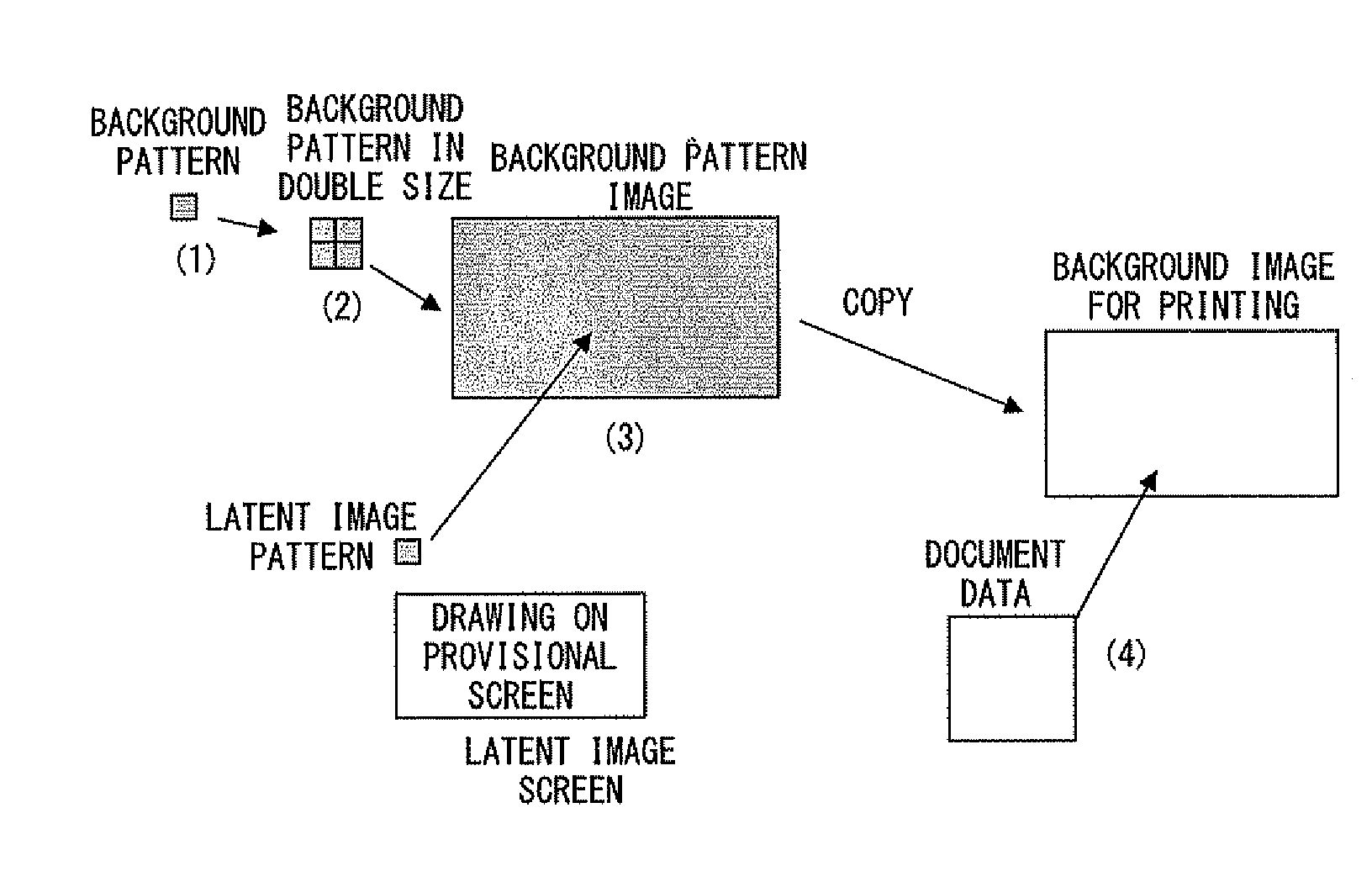
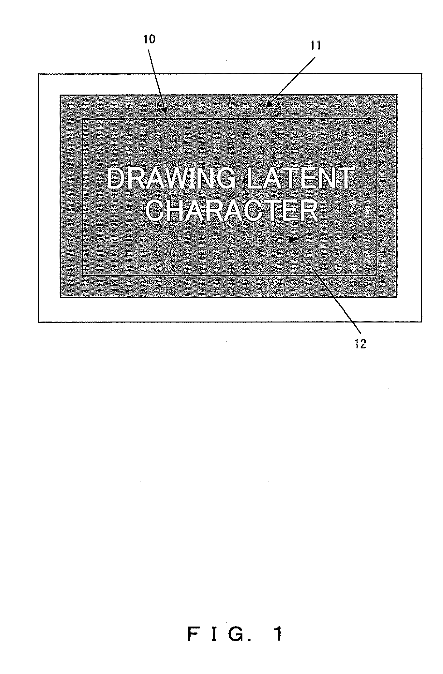
[0045]To solve the above-mentioned problems detected in the image generating system according to the above-mentioned patent documents 1, 4, and 5, an embodiment of the present invention shows a method of generating a background pattern watermark image with a newly proposed latent image from the following three points of views:

(1) A watermark is to be embedded with the improvement of the efficiency and the detection stability ensured;

(2) With respect to a background pattern, the apparent uniformity after printing is to be improved and a watermark is to be appropriately detected after copying and scanning processes; and

(3) A latent image pattern is to be set such that the density is uniform at printing and copying.

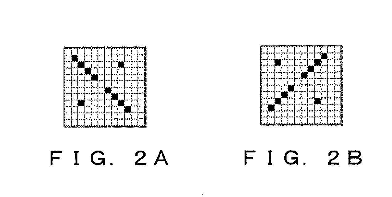
[0046]Relating to the first viewpoint, when watermark information is embedded, a background pattern corresponding to a binary is arranged as an n by m matrix in a constant multiple size (hereinafter referred to as a background pattern in a length by width multiple size), and...


PUM


Abstract

A block where basic units of a background pattern are arranged two-dimensionally is formed so as to stably read buried information from a printed background pattern. Binary or multivalued number is assigned to the block to express information. When a binary number (bit) is assigned to a block made up of background patterns in double size, error correction can be made if an error occurs only in one background pattern while reading the block. In each background pattern, a diagonal lacking its center part is drawn, and isolated dots are placed along the other diagonal. With this, while ensuring the stability of reading the buried information after the read by a scanner, the uniformness of appearance of the printed object can be ensured.

Description

CROSS-REFERENCE TO RELATED APPLICATION[0001]This application is a continuation application of an international patent application No. PCT / JP2005 / 19566, filed on Oct. 25, 2005.BACKGROUND OF THE INVENTION[0002]1. Field of the Invention[0003]The present invention relates to the technology of preventing and suppressing the illegal copy of a document by assigning a background pattern image including a latent image area to a document to be printed, and more specifically to a method of generating a latent image and a background pattern suitable for detection by a scanner device for watermark information embedded in a background pattern area.[0004]2. Description of the Related Arts[0005]A latent image printing technique embeds uniform background patterns in appearance in the background area of a printed document, and specifies a latent image pattern not to be copied in a part of the area of the background pattern when it is copied by a copying machine, thereby suppressing an illegal copy.[0...

Claims


Application Information

Patent Timeline
Patent Type & Authority Applications(United States)
IPC IPC(8): G06K19/06B41J2/00
CPCG06T1/0021H04N1/32203H04N2201/3284H04N2201/3233H04N2201/327H04N1/32208
Inventor MASUI, MOTOOANAN, TAIZO
Owner FUJITSU LTD
Why Eureka
Try Eureka