
Recording medium, optical information device and method for producing recording medium

Inactive Publication Date: 2014-05-15
PANASONIC CORP
View PDF2 Cites 4 Cited by
  • Summary
  • Abstract
  • Description
  • Claims
  • Application Information

AI Technical Summary

Benefits of technology

The patent aims to create a structure that ensures uniform recording intensity and stable information recording or reproduction while reducing variation in reflected light. This is achieved by aligning the structure period of the left-handed material layer with the arrangement period of the recording regions of the recording layer.

Problems solved by technology

However, the improvement on recording density has already reached a limit due to the diffraction limit of light.
As a result, a contact of the recording head with the recording medium may damage the recording head and the recording medium.
Thus, the above technique may cause a problem relating to portability and reliability, which are some of the features of optical media.
However, the left-handed material has anisotropy as well as crystal.
Accordingly, the light collecting characteristics of a small-size light source incorporated with a lens made of a left-handed material are non-uniform depending on the configuration, the surface area, and the light irradiation position of a microstructure which acts on light, and depending on the electromagnetic wave propagation direction.

Method used


Image

  • Recording medium, optical information device and method for producing recording medium
  • Recording medium, optical information device and method for producing recording medium
  • Recording medium, optical information device and method for producing recording medium

Examples


first embodiment

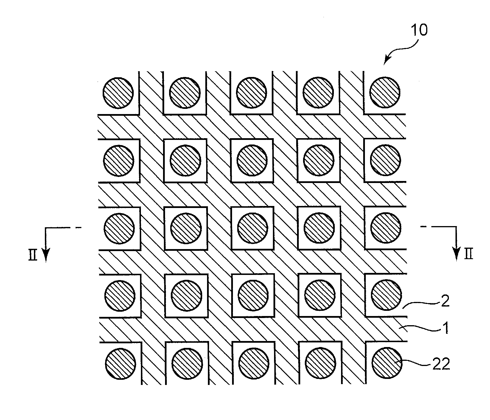
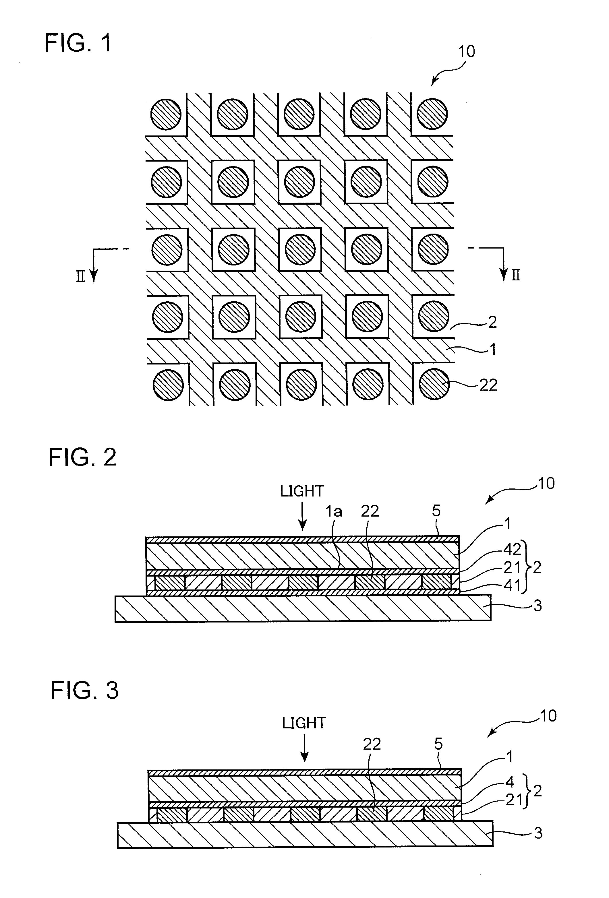
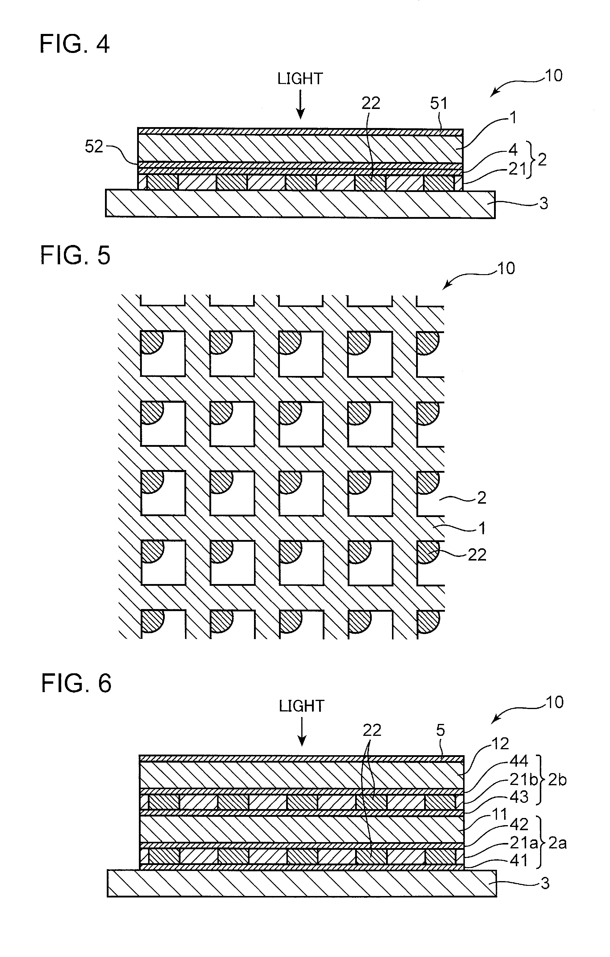
[0051]In the following, a configuration example of a recording medium according to the first embodiment of the invention is described. FIG. 1 is a top plan view showing a configuration of the recording medium according to the first embodiment of the invention. Further. FIG. 2 is a cross-sectional view taken along the line II-II of the recording medium shown in FIG. 1. As shown in FIG. 1 and FIG. 2, a recording medium 10 is provided with a substrate 3 made of a glass material, a recording layer 2 formed on the substrate 3, a left-handed material layer 1 formed on the recording layer 2, and a protection layer 5 formed on the left-handed material layer 1.

[0052]As will be described later, the recording medium 10 may have a protection layer for protecting the recording layer 2 between the recording layer 2 and the left-handed material layer 1.

[0053]The left-handed material layer 1 has at least one of a permittivity and a permeability of a negative value, and has substantially periodicall...

second embodiment

[0086]In the following, there are described a recording method for recording information on the aforementioned recording medium, and a reproducing method for reproducing information from the aforementioned recording medium in the second embodiment.

[0087]FIG. 7 to FIG. 9 are diagrams for describing an example of a recording method for recording information on the recording medium. FIG. 7 is a top plan view showing configurations of the recording medium and an antenna in the second embodiment of the invention. Further, FIG. 8 is a cross-sectional view taken along the line VIII-VIII of the recording medium and the antenna shown in FIG. 7. Further, FIG. 9 is a diagram showing an optical path of light to be incident on the recording medium according to the second embodiment of the invention.

[0088]As shown in FIG. 7 to FIG. 9, light having a polarization direction is irradiated onto an antenna 6 made of Au. Upon irradiation of light, strong near-field light is generated on the apex of the...

third embodiment

[0094]In the following, there is described a method for improving recording characteristics and reproducing characteristics of the aforementioned recording medium in the third embodiment.

[0095]FIG. 10 is a diagram for describing a positional relationship between a recording medium provided with a left-handed material layer using a left-handed material having a fishnet structure, and a light spot in the case where near-field light is used as recording light.

[0096]The light collecting characteristics of small-size light using a left-handed material layer 1 are non-uniform depending on the configuration, the surface area, the light irradiation position of microstructures on which light acts, and depending on the electromagnetic wave propagation direction. A near-field light spot 7 of a size substantially equal to the structure period is irradiated onto the left-handed material layer 1 using a left-handed material having a fishnet structure in this embodiment. At the time of irradiation...


PUM

PropertyMeasurementUnit
Thicknessaaaaaaaaaa
Thicknessaaaaaaaaaa
Structureaaaaaaaaaa

Abstract

A recording medium (10) is provided with a left-handed material layer (1) having at least one of a permittivity and a permeability of a negative value, and having substantially periodically formed structures; and a recording layer (2) including island-shaped and substantially periodically arranged recording regions (22), and being laminated on the left-handed material layer (1). The structure period of the left-handed material layer (1) is equal to or is an integral multiple of the arrangement period of the recording regions (22) of the recording layer (2).

Description

TECHNICAL FIELD[0001]The present invention relates to a recording medium capable of writing and reading information utilizing an optical method, and more particularly to a recording medium, an optical information device, and a method for producing the recording medium utilizing a left-handed material having a negative refractive index.BACKGROUND ART[0002]Nowadays, optical discs as represented by DVDs (Digital Versatile Discs) or BDs (Blu-ray Discs) are widely used as computer-readable recording media and video recording media, utilizing large capacity, random accessibility, portability, and storability, which are some of the features of the optical discs. In recent years, however, as an increase in information quantity accompanied by spread of the Internet, and an increase in information quantity accompanied by high vision TV broadcasting or personal video services have been carried out, there is a demand for a storage suitable for supplying or storing the contents of information. I...

Claims


Application Information

Patent Timeline
IPC IPC(8): G11B7/24027G11B7/24G11B7/24035G11B7/243G11B7/2433G11B7/2437
CPCG11B7/24027G11B2007/24312G11B2007/24314G11B2007/24316G11B7/241Y10T156/10
Inventor FUJINOKI, NORIHITOFURUMIYA, SHIGERUSHIONO, TERUHIRO
Owner PANASONIC CORP
Learn More