Method of recording in an optical information recording medium
a technology of optical information and recording medium, applied in optical recording/reproducing/erasing methods, instruments, photomechanical equipment, etc., can solve problems such as difficult to record and reproduce information stably, and achieve the effect of simple configuration, high-quality reproduced signal and high-quality reproduced signal
- Summary
- Abstract
- Description
- Claims
- Application Information
AI Technical Summary
Benefits of technology
Problems solved by technology
Method used
Image
Examples
first embodiment
(1) First Embodiment
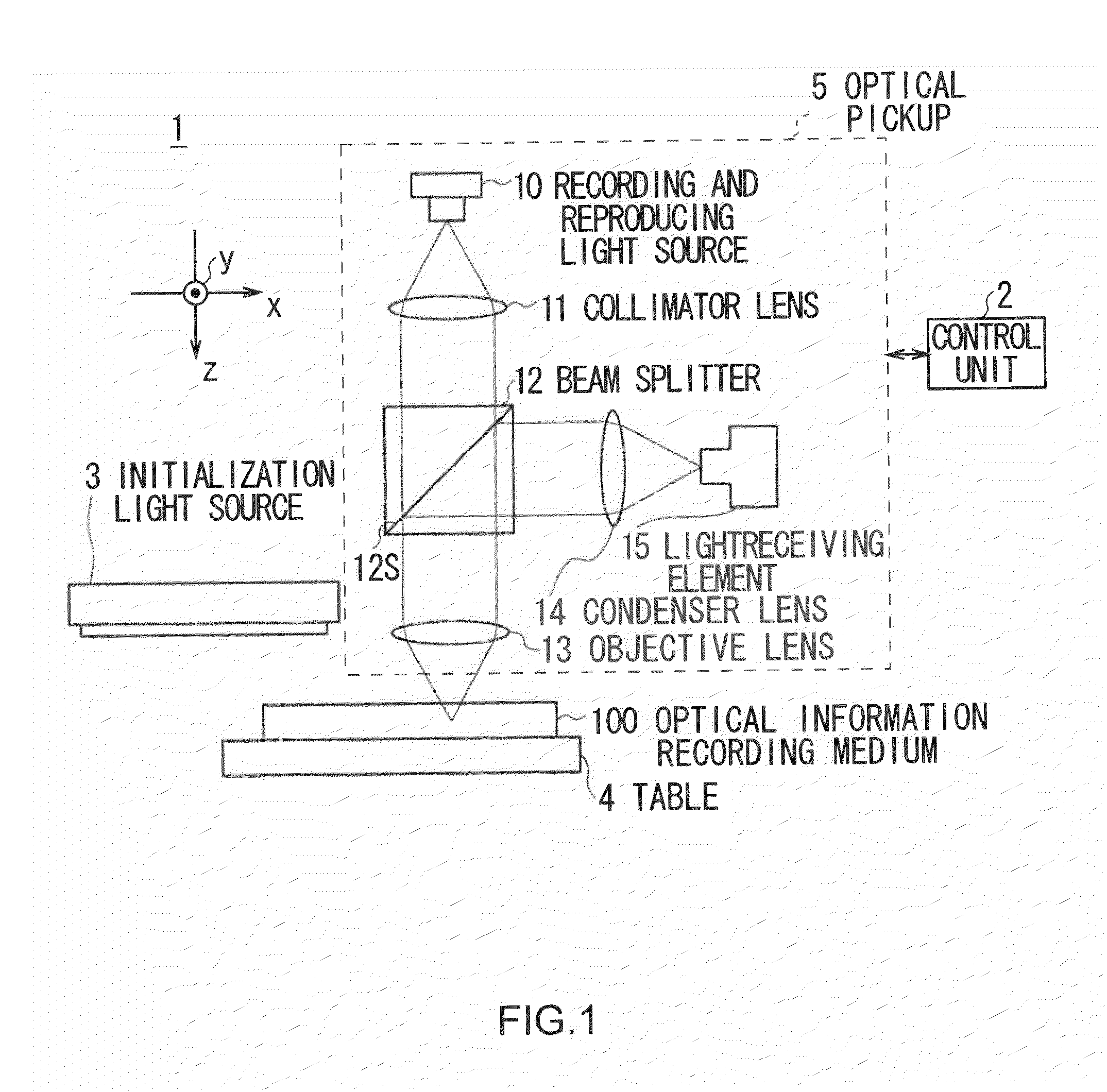
[0038]As shown in FIG. 1, as a whole, an optical information recording and reproducing device 1 according to a first embodiment is so configured as to record information and reproduce thus recorded information by irradiating light to an optical information recording medium 100.
[0039]The optical information recording and reproducing device 1 is totally controlled by a control unit 2 configured by a central processing unit (CPU), which reads out various programs such as a base program, an information recording program, an information reproducing program from a read only memory (ROM), not shown, and expands these programs in a random access memory (RAM), not shown, to execute various processing such as information recording processing and information reproducing processing.
[0040]The control unit 2 controls an initialization light source 3 to make the initialization light source 3 irradiate initialization light L1 of, for example, 532 nm in wavelength, and output the...
second embodiment
(2) Second Embodiment
(2-1) Configuration of Optical Information Recording and Reproducing Device
[0118]As shown in FIG. 9 whose parts have been designated by the same reference symbols and marks as the corresponding parts of FIG. 1, an optical information recording and reproducing device 20 according to a second embodiment, is totally controlled by a control unit 21 corresponding to the control unit 2 (FIG. 1).
[0119]Furthermore, the optical information recording and reproducing device 20 has almost the same configuration as that of the optical information recording and reproducing device 1 (FIG. 1). Instead of the optical pickup 5 having a recording and reproducing light source 10 and the objective lens 13, the optical information recording and reproducing device 20 includes an optical pickup 25 having a recording and reproducing light source 22 and an objective lens 23 and excludes the initialization light source 3.
(2-2) Configuration of Optical Information Recording Medium
[0120]On ...
third embodiment
(3) Third Embodiment
(3-1) Configuration of Optical Information Recording and Reproducing Device
[0160]As shown in FIG. 17 whose parts have been designated by the same reference symbols and marks as the corresponding parts of FIG. 1, an optical information recording and reproducing device 30 according to a third embodiment, is totally controlled by a control unit 31 corresponding to the control unit 2 (FIG. 1).
[0161]Furthermore, the optical information recording and reproducing device 30 has almost the same configuration as that of the optical information recording and reproducing device 1 (FIG. 1). Instead of the optical pickup 5 having the recording and reproducing light source 10 and the objective lens 13, the optical information recording and reproducing device 30 includes an optical pickup 35 having a recording and reproducing light source 32 and an objective lens 33 and excludes the initialization light source 3.
(3-2) Configuration of Optical Information Recording Medium
[0162]In...
PUM
| Property | Measurement | Unit |
|---|---|---|
| wavelength | aaaaa | aaaaa |
| wavelength | aaaaa | aaaaa |
| thickness | aaaaa | aaaaa |
Abstract
Description
Claims
Application Information
 - R&D
- Intellectual Property
- Life Sciences
- Materials
- Tech Scout
- Unparalleled Data Quality
- Higher Quality Content
- 60% Fewer Hallucinations
Browse by: Latest US Patents, China's latest patents, Technical Efficacy Thesaurus, Application Domain, Technology Topic, Popular Technical Reports.
© 2025 PatSnap. All rights reserved.Legal|Privacy policy|Modern Slavery Act Transparency Statement|Sitemap|About US| Contact US: help@patsnap.com


