Voice coil motor

Inactive Publication Date: 2008-08-21
JOHNSON ELECTRIC INTERNATIONAL AG
View PDF5 Cites 41 Cited by
  • Summary
  • Abstract
  • Description
  • Claims
  • Application Information

AI Technical Summary

Benefits of technology

[0007]Thus, it is an object of the present invention to provide a

Problems solved by technology

One problem with current voice coil motor driven modules is that it is difficult to further reduce the overall size of the module, yet maintain the lens size and still improve the performance, in particular, the response time of the module to achieve

Method used


Image

  • Voice coil motor
  • Voice coil motor
  • Voice coil motor

Examples


Example

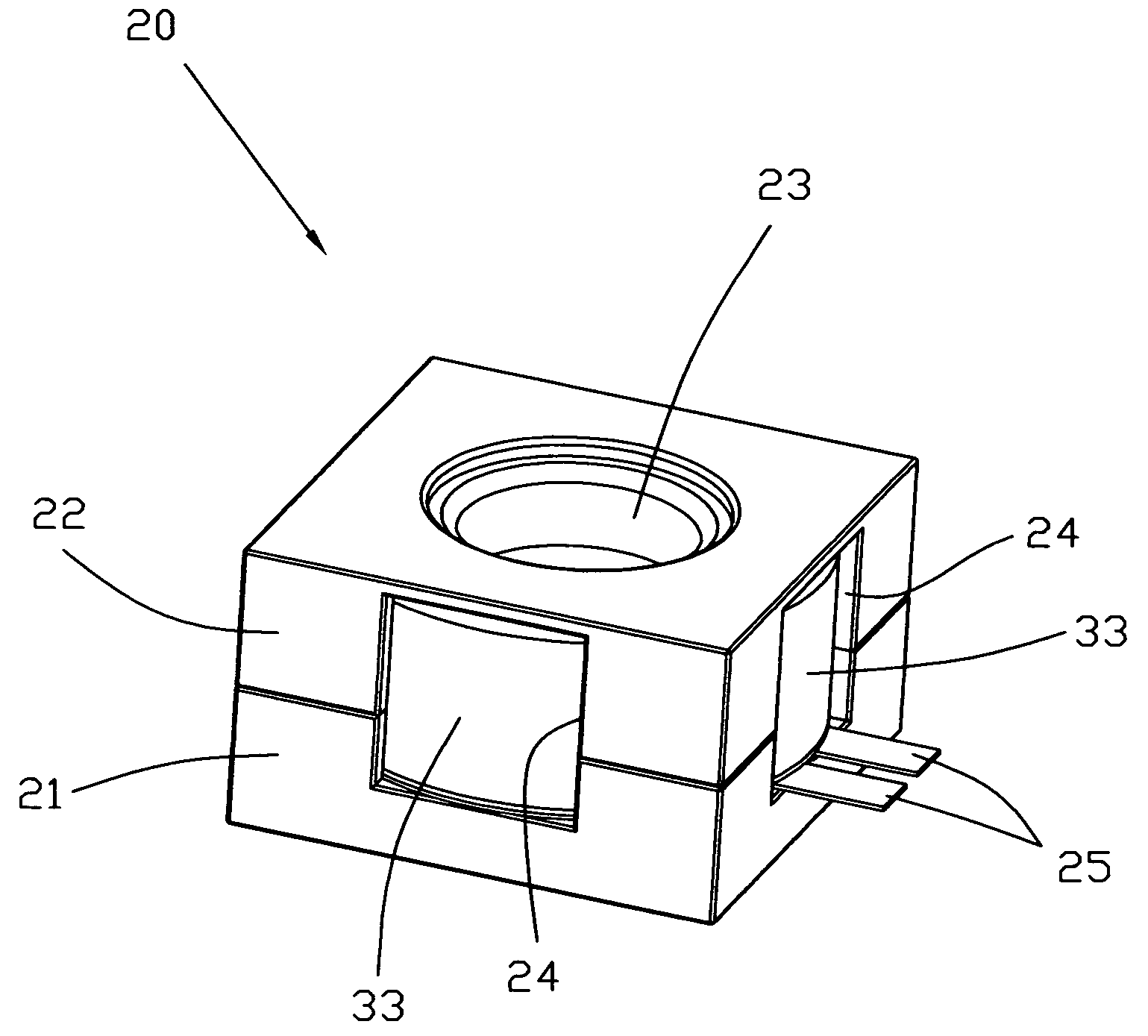
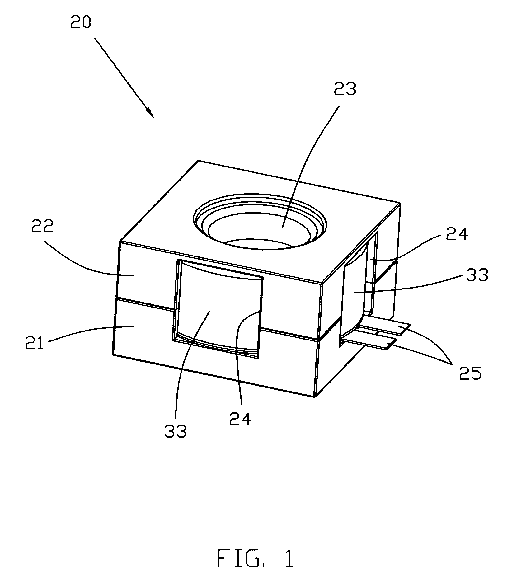
[0051]The preferred lens module 20 is shown assembled in FIG. 1 and exploded in FIG. 2. The outer appearance of the module 20 is like a squat square box measuring 8.5 by 8.5 by 5 mm. The module 20 has a two part casing with a lower case 21 and an upper case 22. The upper case 22 has a central hole 23 through which light for an image to be captured can pass. Additional openings 24 are formed in each side, formed by cutouts in the joining edges of the upper and lower cases. Through one of the side openings, two terminals 25 protrude for connecting the module 20 to a source of power. A magnet housing 33 can be seen through the side openings 24.

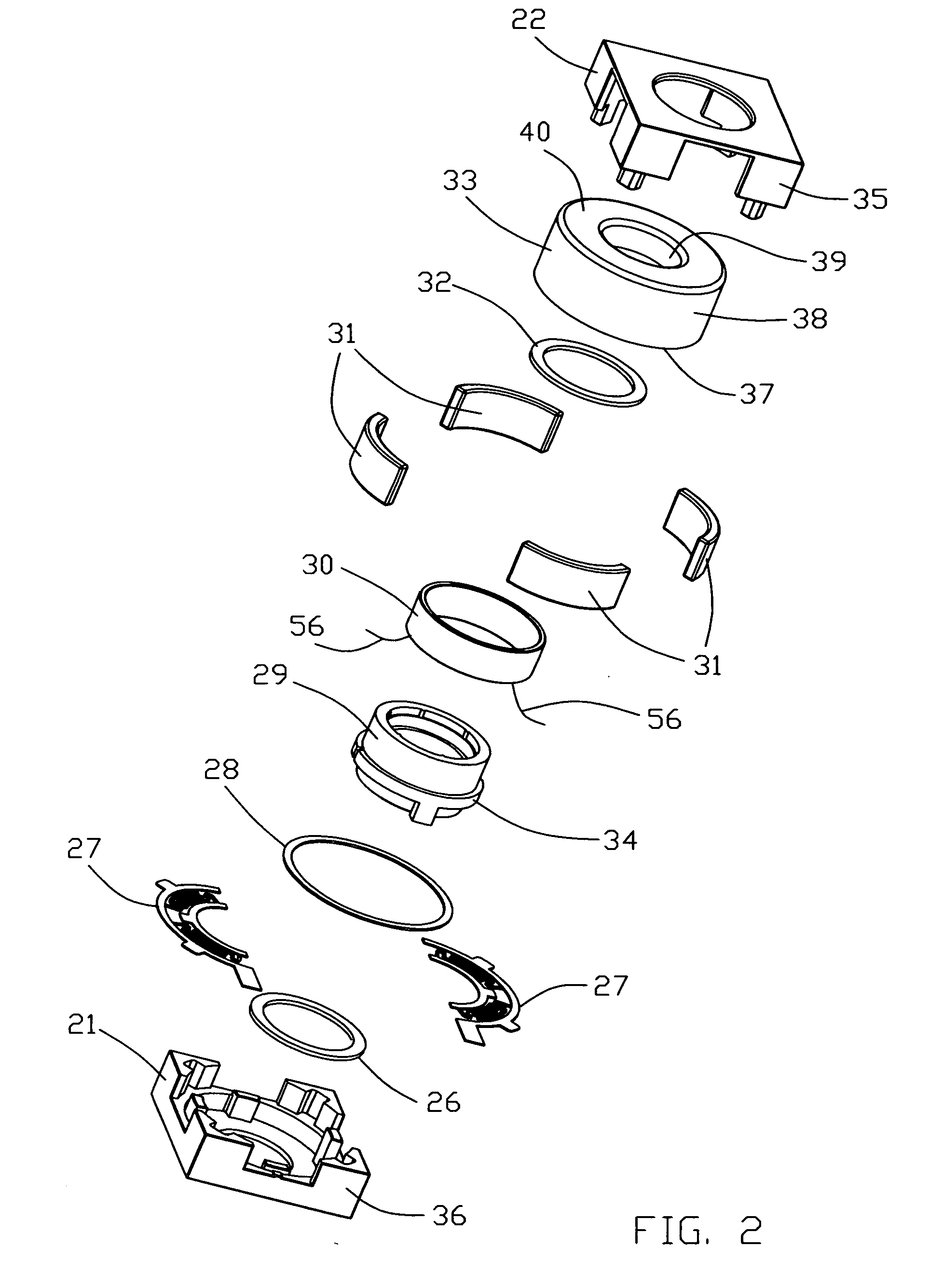
[0052]Referring to the exploded view of FIG. 2, the components of the module 20 will be named starting from the bottom. At the bottom is the lower case 21. Fixed to the floor of the lower case 21 is a lower cushion 26. Fitted or placed into the lower case are two springs 27. An insulating ring 28 is placed on top of an outer edge of the springs 2...


PUM


Abstract

A voice coil motor lens module has a two part casing accommodating a magnet housing of annular form with an outer wall and an inner wall joined by a top wall. One or more magnets producing a magnetic field, are fitted to the inner surface of the outer wall. A lens holder, for supporting a lens, has a coil fitted to an outer surface thereof and is suspended by a pair of springs such that the coil is disposed within the magnetic field. The lens holder has an inner bore and an axially upper end. The inner wall extends into the inner bore of the lens holder and the upper end of the lens holder rests, in a park position, against an upper cushion fixed to an inner surface of the top wall. In use, current passing through the coil moves the lens holder downwardly to focus an image on an image sensor below the lens holder. At a fully extended position, the lower end of the lens holder rests against a lower cushion fixed to the casing.

Description

CROSS-REFERENCE TO RELATED APPLICATIONS [0001]This non-provisional patent application claims priority under 35 U.S.C. §119(a) from Patent Application No. 0702897.0 filed in Great Britain on 15 Feb. 2007.BACKGROUND OF THE INVENTION [0002]Lens modules, especially autofocus lens modules, have a lens holder to which is mounted a single lens or lens assembly, simply referred to herein as a lens, for focussing an image onto an image plane. In use, the image plane would be an image sensor such as a CMOS or CCD device but in practice, the lens module is produced bare, meaning without the lens and without the image sensor which are fitted by the camera module maker. The lens module has a lens holder which is arranged to be driven by an actuator along a short straight path. Known actuators include DC motors, stepping motors, voice coil motors, ultrasonic motors and electrostrictive actuators including piezoelectric actuators.[0003]There is a strong demand for small lens modules as small camer...

Claims


Application Information

Patent Timeline
IPC IPC(8): G02B13/16
CPCG02B7/08H02K41/0356G03B3/10H02K33/18
Inventor NAGASAKI, YASUMASA
Owner JOHNSON ELECTRIC INTERNATIONAL AG
Why Eureka
Try Eureka